Rainwater storage and collection device for landscaping

A landscaping and rainwater storage technology, which is applied in the field of rainwater storage devices, can solve the problems of unable to automatically clean up fallen leaves and impurities, blockage of pipes, and affecting rainwater collection, so as to ensure smoothness, reduce residues, and facilitate disassembly and installation. Effect

Pending Publication Date: 2021-01-12
NANJING FORESTRY UNIV
View PDF8 Cites 3 Cited by
  • Summary
  • Abstract
  • Description
  • Claims
  • Application Information

AI Technical Summary

Problems solved by technology

[0003] The existing patent No. CN 206646577 U discloses a rainwater collection device for gardens, which includes a sleeve surrounding the trunk of garden trees, a foldable umbrella collector mounted on the sleeve, and a And a water storage tank for storing rainwater collected by the collapsible umbrella-shaped collector; the collapsible umbrella-shaped collector includes a collar slidingly sleeved on the peripheral surface of the sleeve, and an umbrella-shaped part connected to the collar through a connecting rod , the two ends of the connecting rod are respectively hinged with the collar and the umbrella; the bottom of the water storage tank is inserted into the soil around the trunk of the garden tree through the support tube, and the rainwater collected by the foldable umbrella collector is stored in the water storage tank Among them, the rainwater stored in the water storage tank is discharged into the soil around the garden trees through the support pipes, so as to better water the garden trees, which facilitates garden irrigation and effectively saves water resources. However, the applicant believes that The rainwater collection device in the above application cannot automatically clean up fallen leaves and impurities. During the long-term collection process, it is easy to cause the possibility of pipe blockage in the device, thereby affecting the collection of rainwater, and the collected rainwater cannot be recycled.

Method used


Image

  • Rainwater storage and collection device for landscaping
  • Rainwater storage and collection device for landscaping
  • Rainwater storage and collection device for landscaping

Examples


Embodiment 1

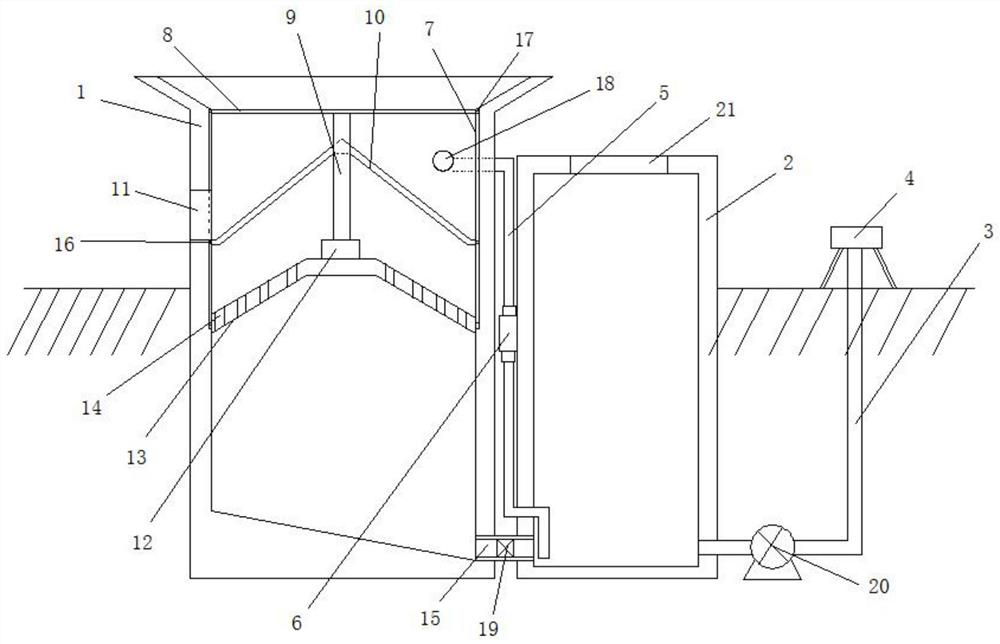
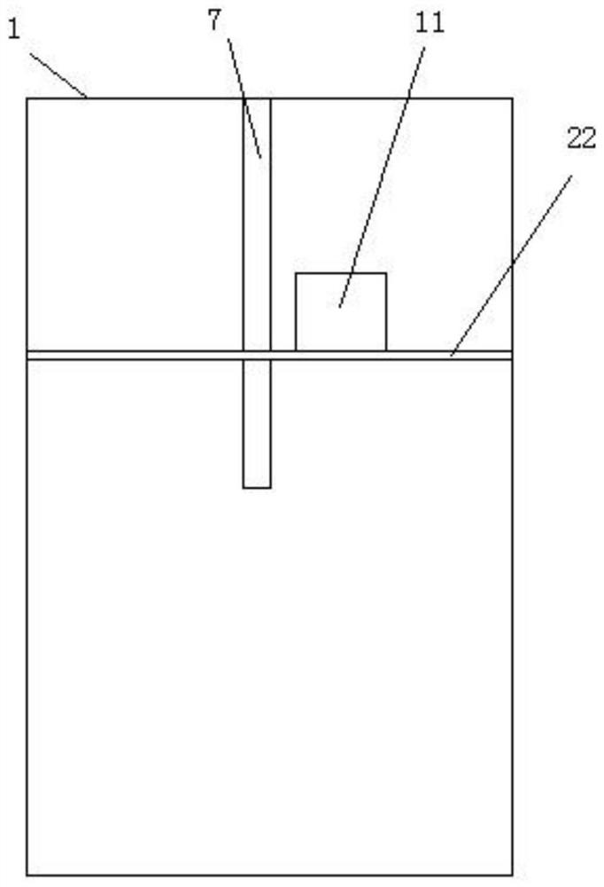
[0022] A rainwater storage device for landscaping, including a collection cylinder 1, a storage cylinder 2, an irrigation pipe 3 and a sprinkler head 4. A transparent window 21 is arranged at the center of the top of the storage cylinder 2, so that the storage cylinder 2 can be accurately and intuitively grasped. For the storage of rainwater, the collection cylinder 1 flows the filtered rainwater into the storage cylinder 2 for storage, and the rainwater in the storage cylinder 2 is sprayed out through the irrigation pipe 3 and the sprinkler head 4 to complete the irrigation. The inner cavity of the collection cylinder 1 is provided with a rotating groove 22, and the turning groove 22 intersects with the limit groove 7, and the left and right ends of the screen 10 are provided with a rotating block 16 that matches the turning groove 22, and the screen 10 is arranged in an inverted funnel shape, which is convenient for the limit of the screen 10. Bit rotation, also can leaf and ...

Embodiment 2

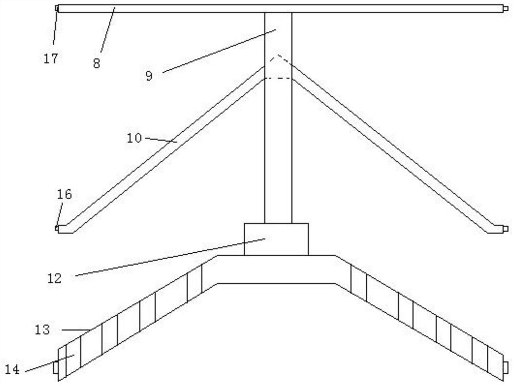
[0024] The difference between the second embodiment and the first embodiment is that a limit groove 7 is provided between the left and right side walls of the inner cavity of the collection tube 1, and the left and right ends of the support cross bar 8 and the left and right ends of the support seat 13 are provided with The limit block 17 matched with the limit groove 7 can disassemble and install the support cross bar 8 and the support seat 13 like this, and also plays the role of limit guide for the support cross bar 8 and support seat 13 simultaneously.

[0025] Working principle: install the device, insert the connecting body composed of the support bar 8, the rotating shaft 9, the screen 10 and the support seat 13 into the limit groove 7 of the inner cavity side wall of the collection tube 1, the limit block 17 and the limit The bit groove 7 is installed in cooperation, so that the support cross bar 8 and the support seat 13 are disassembled and installed. After the instal...


PUM


Abstract

The invention discloses a rainwater storage and collection device for landscaping. The rainwater storage and collection device comprises a collection barrel, a storage barrel, an irrigation pipe and aspray-irrigation head, the collection barrel enables filtered rainwater to flow into the storage barrel to be stored, the rainwater in the storage barrel is sprayed out through the irrigation pipe and the spray-irrigation head, a supporting cross rod is connected to an opening of the collection barrel in an inserted mode, a supporting seat is connected into an inner cavity, below the supporting cross rod, of the collection barrel in an inserted mode, flow-guiding holes are formed in the surfaces of the left section and the right section of the supporting seat correspondingly, a rotating motoris arranged at the top of the center of the supporting seat, the power output end of the rotating motor is connected with a rotating shaft, a screen net is fixedly connected to the rotating shaft between the supporting cross rod and the supporting seat, the screen net is rotationally connected with the side wall of the inner cavity of the collection barrel, a slag outlet is formed in the left side wall of the collection barrel, and a connecting pipe is arranged between the right side of the collection barrel and the left side of the storage barrel in a communicating mode. The rainwater storage and collection device is reasonable in design structure, fallen leaves and impurities can be automatically cleared, the possibility of pipeline blockage in the device is reduced, and meanwhile, therainwater can also be recycled.

Description

technical field [0001] The invention relates to the technical field of rainwater storage devices, in particular to a rainwater storage device for landscaping. Background technique [0002] Planting trees, planting grass and flowers in a fixed area, covering or decorating a certain ground (space), this is a garden, which is an important property of planting plants to improve the surrounding environment and the quality of the living environment of the surrounding residents. In the design process, it is generally necessary to design a rainwater collection device, and use the rainwater collection device to collect rainwater, so as to effectively protect and utilize water resources. [0003] The existing patent No. CN 206646577 U discloses a rainwater collection device for gardens, which includes a sleeve surrounding the trunk of garden trees, a foldable umbrella collector mounted on the sleeve, and a And a water storage tank for storing rainwater collected by the collapsible um...

Claims


Application Information

Patent Timeline
Patent Type & Authority Applications(China)
IPC IPC(8): E03B3/02E03B11/14A01G25/02B01D33/15
CPCE03B3/02E03B11/14A01G25/02B01D33/15Y02A20/108
Inventor 申世广李雨薇张佩瑶吴程程
Owner NANJING FORESTRY UNIV
Why Eureka
Try Eureka