
Machining system and machining method for spot facing

A processing system and surface facing technology, applied in metal processing equipment, manufacturing tools, components of boring machines/drilling machines, etc., can solve the problems of shape and position tolerance and surface roughness out of tolerance, large machining dimensional tolerance, etc., to achieve accurate depth of cut The effect of dimensional limit, high dimensional accuracy, and smooth and correct cutting state

Active Publication Date: 2021-07-13
SHAANXI FAST AUTO DRIVE GROUP CO LTD
View PDF8 Cites 1 Cited by
  • Summary
  • Abstract
  • Description
  • Claims
  • Application Information

AI Technical Summary

Problems solved by technology

[0003] The purpose of the present invention is to solve the problems of large processing size tolerance, shape and position tolerance and surface roughness of existing countersinking planes, and to provide a processing system and processing method for countersinking planes

Method used


Image

  • Machining system and machining method for spot facing
  • Machining system and machining method for spot facing
  • Machining system and machining method for spot facing

Examples


Embodiment Construction

[0035] The following will clearly and completely describe the technical solutions in the embodiments of the present invention with reference to the drawings in the embodiments of the present invention.

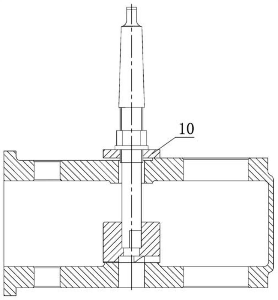
[0036] The invention provides a processing system and processing method for countersinking. The system also associates tools, fixtures and workpieces in the cutting process, so that the tools can respectively establish a cooperative relationship with the fixtures and workpieces, and realize a stable and correct cutting state and accurate cutting. The cutting depth size limit makes the dimensional accuracy after processing higher, so that the product quality of the spot facing inner cavity plane process is completely qualified and meets the design requirements.

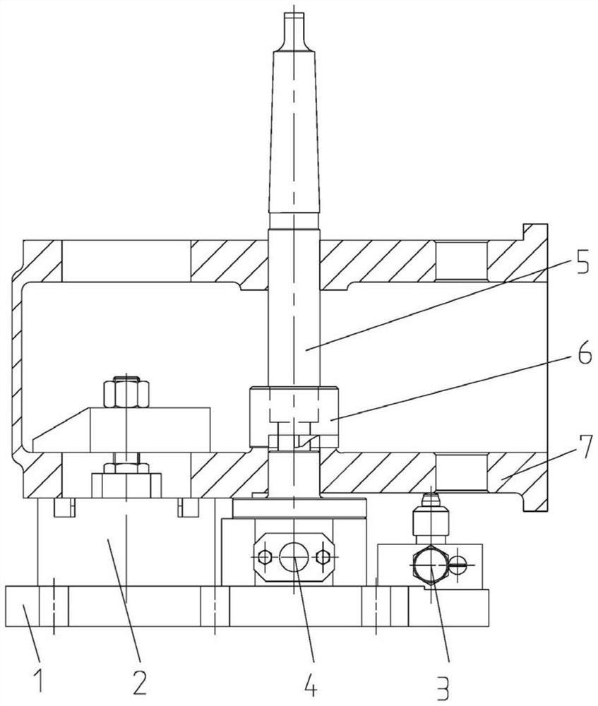
[0037] Such as image 3As shown, the processing system for spot facing of the present invention includes a clamp unit and a tool unit; the clamp unit includes a clamp base plate 1, a positioning and pressing assembly 2...


PUM


Abstract

The invention provides a machining system and a machining method for spot facing and solves the problems that during existing spot facing, the machining dimensional tolerance is large, and the form and location tolerance and surface roughness are out of tolerance greatly. The machining system comprises a clamp unit and a cutter unit. The clamp unit comprises a clamp bottom plate, a positioning and pressing assembly, an auxiliary supporting assembly and a positioning and guiding assembly. The positioning and pressing assembly is arranged between the clamp bottom plate and a workpiece, connected with the clamp bottom plate and the workpiece and used for fixedly installing the workpiece. The auxiliary supporting assembly is arranged between the clamp bottom plate and the workpiece, one end of the auxiliary supporting assembly is connected with the clamp bottom plate, and the other end of the auxiliary supporting assembly abuts against the side wall of the workpiece and is used for adjusting the relative position between the clamp bottom plate and the workpiece. The positioning guide assembly is arranged between the clamp bottom plate and the workpiece, one end of the positioning guide assembly is connected with the clamp bottom plate, and the other end of the positioning guide assembly is connected with the workpiece and used for positioning the plane and an inner hole of the workpiece. The cutter unit comprises a cutter bar and a cutter body, the cutter bar is sleeved with the cutter body, and the cutter body is used for spot facing.

Description

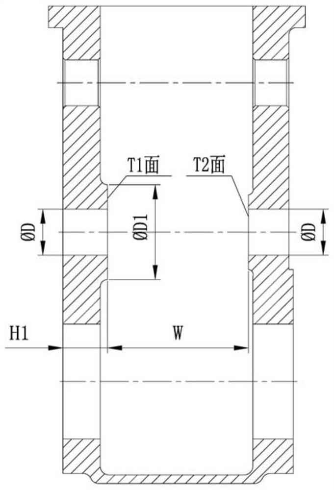
technical field [0001] The invention belongs to the field of hole processing, and in particular relates to a processing system and method for countersinking planes. Background technique [0002] At present, when machining the inner surface of the hole of the workpiece, tools such as countersinking tools and counter boring tools are generally used. Such as figure 1 As shown, when the power take-off shell is spot facing the inner cavity plane, the technological plan of the cutting process is only related to the tool, and has nothing to do with the fixture and the workpiece. The surface roughness is out of tolerance. The causes of the above problems are as follows: 1) Insurmountable objective reasons: the manufacturability of the inner surface of the workpiece is relatively poor compared to the manufacturability of the outer surface of the workpiece, and more due to figure 1 ΦD1 / ΦD>2, the process plan of using back-boring tool on automatic equipment cannot be adopted. Only o...

Claims


Application Information

Patent Timeline
IPC IPC(8): B23B51/10B23B35/00
CPCB23B51/101B23B51/102B23B35/00
Inventor 梁宝忠严鉴铂寇植达刘心民李峰
Owner SHAANXI FAST AUTO DRIVE GROUP CO LTD
Learn More