Quick disassembly and assembly type ship-borne navigation equipment and use method thereof
A kind of navigation equipment and disassembly technology, which is applied to waterborne ship navigation equipment, electrical equipment structural parts, ships, etc. problems, to achieve the effect of reducing temperature, improving work stability, and improving disassembly and assembly efficiency
- Summary
- Abstract
- Description
- Claims
- Application Information
AI Technical Summary
Problems solved by technology
Method used
Image

Examples
Embodiment 1
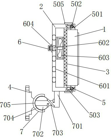
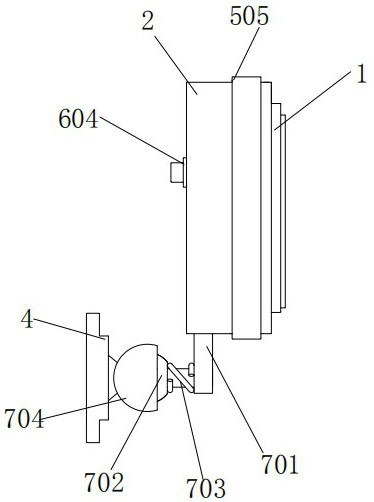
[0031] A quick-dismantling shipborne navigation device, comprising a navigation device 1, the left side of the navigation device 1 is provided with a mounting frame 2, the left side of the inner wall of the mounting frame 2 is matched with the outer wall of the navigation device 1, and the left side of the navigation device 1 A filter screen 3 is provided, and the filter screen 3 is a stainless steel ten-mesh filter screen. The outer wall of the filter screen 3 is fixedly connected with the inner wall of the installation frame 2. The right end of the filter screen 3 is tightly connected to the left end of the navigation device 1. A mounting plate 4 is provided, and a connecting component 5 is provided between the mounting frame 2 and the navigation device 1 .
[0032] The connection assembly 5 includes a through groove 501, a round rod 502, a limit bayonet 503, a torsion spring 504, a square collar 505, a wedge-shaped protrusion 506 and a rectangular block 507. The through groo...
Embodiment 2
[0034] As an option, see figure 1 , 2, 5 and 6, quick disassembly type shipborne navigation equipment, the left side of the installation frame 2 is provided with a cooling assembly 6, the cooling assembly 6 includes a spiral chute 601, a slider 602, a cooling fan 603, a limit turn block 604 and Grinding pattern 605, spiral chute 601 is processed on the left end of mounting frame 2, and the inside of spiral chute 601 is provided with slider 602, the outer wall of slider 602 is matched with the inner wall of spiral chute 601, and the spiral chute The inner wall of 601 matches the shape of the outer wall of the slider 602, and the spiral chute 601 and the slider 602 form a sliding structure. The helical chute 601 can make the slider 602 slide when it is stressed. The right end of the slider 602 is provided with Radiating fan 603, the left end of cooling fan 603 is fixedly connected with the right end of slide block 602, and the left side of slide block 602 is provided with limit...
Embodiment 3
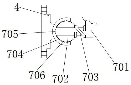
[0037] As an option, see Figure 1-3 , quick disassembly shipboard navigation equipment, between the installation frame 2 and the installation plate 4 is provided with an adjustment assembly 7, the adjustment assembly 7 includes a curved rod 701, a ball 702, a tension spring 703, a ball sleeve 704, a convex edge 705 and a concave Groove 706, curved rod 701 is positioned at the bottom of mounting frame 2, and the top of curved rod 701 is fixedly connected with the bottom left side of mounting frame 2, and the left side of curved rod 701 is provided with ball 702, and the inner wall of ball 702 and the outer wall of curved rod 701 The left side is clearance fit, the outer wall of the curved rod 701 is sleeved with a tension spring 703, the left end of the tension spring 703 is fixedly connected with the right end of the ball 702, and the right end of the tension spring 703 is fixedly connected with the corner of the curved rod 701, stretching The spring 703 gives the force to th...
PUM
 Abstract
Description
Claims
Application Information
 - R&D
- Intellectual Property
- Life Sciences
- Materials
- Tech Scout
- Unparalleled Data Quality
- Higher Quality Content
- 60% Fewer Hallucinations
Browse by: Latest US Patents, China's latest patents, Technical Efficacy Thesaurus, Application Domain, Technology Topic, Popular Technical Reports.
© 2025 PatSnap. All rights reserved.Legal|Privacy policy|Modern Slavery Act Transparency Statement|Sitemap|About US| Contact US: help@patsnap.com