
A batch steel plate flip device system

A technology of flipping device and steel plate, which is applied in transportation and packaging, conveyor objects, conveyors, etc., can solve the problems of cumbersome operation, long time, and large steel plate area.

Active Publication Date: 2022-08-09
四川兴事发门窗有限责任公司
View PDF7 Cites 0 Cited by
  • Summary
  • Abstract
  • Description
  • Claims
  • Application Information

AI Technical Summary

Problems solved by technology

[0002] The steel plate needs to be processed, polished, punched, etc. on the front and back sides. Due to the large area of ​​the steel plate, it cannot be transported manually. It is usually moved by driving or turned over by a crane. However, the operation of driving and crane is cumbersome and requires the cooperation of multiple people. It takes a long time and is efficient. Low, the operation hidden danger is great, and it is easy to scratch the workers; and the steel plate used to make the fire door is usually thin, and the quality is relatively low
Usually, during the processing of steel plates, multiple stacked steel plates need to be turned over as a whole. If the existing steel plate turning device is used, the stacked steel plates need to be packed or bundled when turning over the steel plates to ensure that the stacked steel plates are During the overturning process, there is no offset between the steel plate and the steel plate, so as to ensure that the posture of the steel plate does not need to be adjusted during the subsequent clamping and processing of the steel plate. However, if the packing or bundling method is adopted, the packing belt or trapped The rope is removed, which takes a long time and is cumbersome to operate

Method used


Image

  • A batch steel plate flip device system
  • A batch steel plate flip device system
  • A batch steel plate flip device system

Examples


Embodiment 1

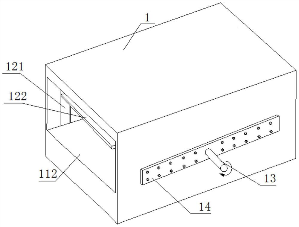
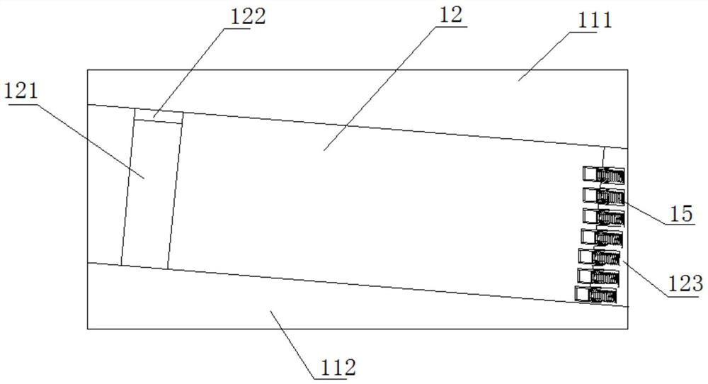
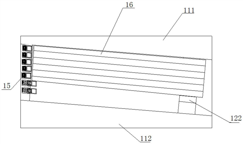
[0024] join Figure 1 to Figure 4 , the overall shape of the overturning device body 1 has a rectangular parallelepiped structure, and there is a accommodating cavity 12 extending through the overturning device body 1 , the accommodating cavity 12 is a parallelogram cavity, and the accommodating cavity 12 is a parallelogram cavity. The height is a multiple of the thickness of the steel plate 16, the width of the accommodating cavity 12 is slightly larger than the width of the steel plate 16, the inlet end of the accommodating cavity 12 is higher than the outlet end thereof, and the outlet end of the accommodating cavity 12 is provided with a limit plate 123, the inner surface of the limiting plate 123 is perpendicular to the top, bottom and side walls of the accommodating cavity 12, the limiting plate 123 may not completely cover the outlet end of the accommodating cavity 12, so as to facilitate stacking After the steel plate 16 is turned over, the pushing device extends into ...

Embodiment 2

[0026] like Figure 1 to Figure 4As shown, Embodiment 2 is based on Embodiment 1. The center of both sides of the turning device body 1 is provided with a rotating shaft 13, the rotating shafts 13 rotate synchronously and in the same direction, and the performance of the rotating shaft 13 is sufficient to support the turning device body. 1 rotation; a booster plate 14 is provided between the rotating shaft 13 and the outer surface of the turning device body 1, and the booster plate 14 and the rotating shaft 13 are integrally formed in a structure to increase its strength, and the booster plate 14 passes through A plurality of fasteners are fixed to the body 1 of the overturning device; a chute 121 is opened inside the accommodating cavity 12 , the length direction of the chute 121 is perpendicular to the bottom surface of the accommodating cavity 12 , and the height of the chute 121 is greater than The height of the accommodating cavity 12, the lifting plate 122 can cooperate ...

Embodiment 3

[0030] like Figure 5 As shown, Embodiment 3 is based on Embodiment 1, and the structure of the inversion device body 1 can also adopt another implementation manner, the difference is that the inversion device body 1 is divided into two oppositely arranged parts, and the two parts It can be a single structure or can be connected by a connecting plate or a connecting plate, as long as the two parts can rotate in the same direction and synchronously; the body 1 of the overturning device is also provided with an accommodating cavity 12, and the accommodating cavity 12 is two parts. The relative areas between the parts are combined, and both the top surface and the bottom surface of the accommodating cavity 12 can play a role in receiving the pallets; another embodiment is: the accommodating cavity 12 on both sides of the The side is provided with a frame structure such as a stop bar, which can also achieve a lateral restraint effect on the stacking steel plates 16 .


PUM


Abstract

The invention discloses a batch steel plate inverting device system, comprising: the inverting device body is disposed between the front-end conveying device and the rear-end conveying device, a accommodating cavity is opened inside the inverting device body, and the top surface and the bottom surface are formed from the top surface and the bottom surface. The inlet end to its outlet end is inclined from top to bottom; the front end conveying device is aligned with the inlet end of the accommodating cavity and is higher than the inlet end, and the rear end conveying device is opposite to the outlet end of the accommodating cavity The outlet end of the accommodating cavity is provided with a limiting plate, and the body of the overturning device can rotate around the vertical line of its own length direction. The present invention only needs to push the stacking steel plate into the accommodating cavity by means of pushing, and after turning over, push the stacking steel plate to the top of the rear end conveying device by means of pushing, thereby avoiding the need for installation and installation in the prior art. The flipping steel plate needs to be clamped, grasped, and hoisted, which requires more equipment, relatively complicated operation, and low operation safety.

Description

technical field [0001] The invention relates to the technical field of a steel plate turning device for fire doors, in particular to a batch steel plate turning device system. Background technique [0002] The steel plate needs to be processed, polished, punched, etc. on the front and back. Due to the large area of ​​the steel plate, manual handling cannot be carried out. Generally, it is moved by a crane or turned over by a crane. However, the operation of the crane and the crane is troublesome, and requires the cooperation of many people. It takes a long time and is efficient. Low, high operating hidden dangers, easy to scratch workers; while the steel used for fire doors, usually thin, relatively low quality. Usually, in the process of steel plate processing, it is necessary to turn a plurality of stacked steel plates as a whole. If the existing steel plate turning device is used, the stacked steel plates need to be packed or bundled when turning the steel plates to ensur...

Claims


Application Information

Patent Timeline
Patent Type & Authority Patents(China)
IPC IPC(8): B65G47/252
CPCB65G47/252B65G2201/022
Inventor 黄仁辉何杰林
Owner 四川兴事发门窗有限责任公司
Learn More