Tunnel heading machine and gripper shoe device thereof

A technology for tunnel boring machines and tunnels, which is applied in tunnels, mining equipment, earthwork drilling and mining, etc. It can solve the problems of weak and broken surrounding rock areas that cannot be effectively supported, and the support area is fixed, so as to improve the passing rate and increase the support. Top area, effect of reducing reaction force

Active Publication Date: 2021-07-13
CHINA RAILWAY ENGINEERING EQUIPMENT GROUP CO LTD
View PDF9 Cites 2 Cited by
  • Summary
  • Abstract
  • Description
  • Claims
  • Application Information

AI Technical Summary

Problems solved by technology

[0007] The purpose of the present invention is to provide a support shoe device for tunnel boring machines to solve the problem in the prior art that the roof support area of ​​the roof tunnel must cause the support shoes normally used in the hard rock area to be unable to effectively support the weak and broken surrounding rock area. technical problem
At the same time, the present invention also provides a tunnel boring machine using the above-mentioned support shoe device to solve the technical problem in the prior art that the support area is fixed and the weak and broken surrounding rock area cannot be effectively supported to provide effective support reaction force.

Method used


Image

  • Tunnel heading machine and gripper shoe device thereof
  • Tunnel heading machine and gripper shoe device thereof
  • Tunnel heading machine and gripper shoe device thereof

Examples


specific Embodiment 1

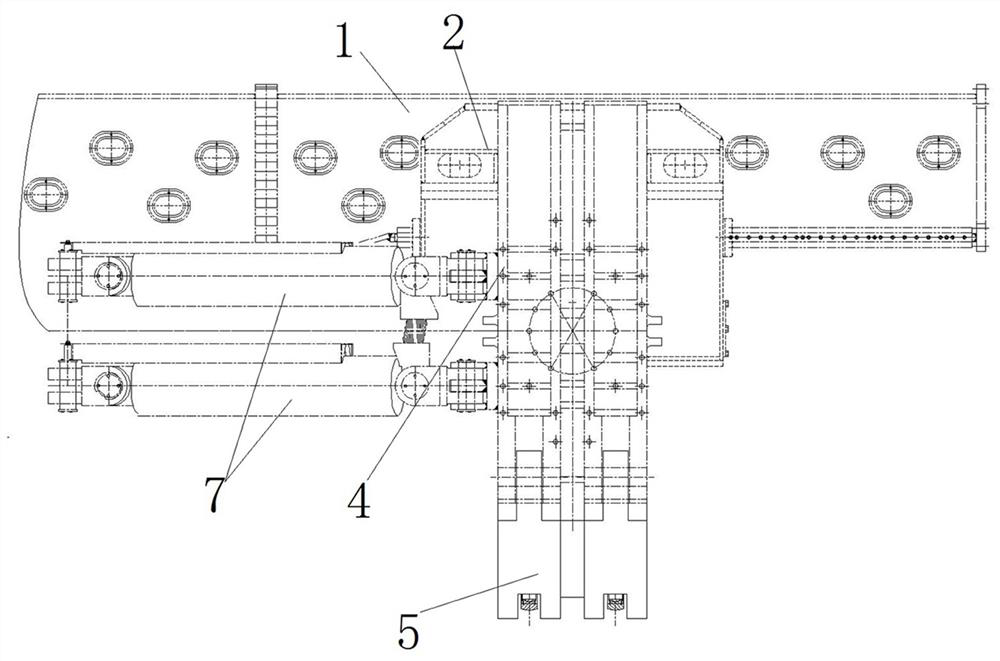
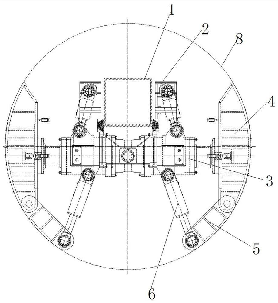
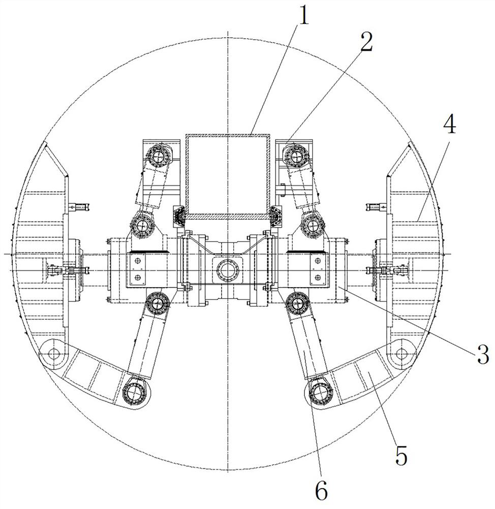
[0053] Such as figure 1 , figure 2 and image 3 As shown, the tunnel boring machine in this embodiment is an open TBM, and the TBM includes a main beam 1 , a main drive is provided at the front end of the main beam 1 , and the main drive is used to drive the cutter head to rotate to excavate a tunnel 8 . Wherein, the structures of the main beam 1 , the main drive and the cutter head are the same as those of the main beam 1 , the main drive and the cutter head of the TBM in the prior art, and will not be repeated here.

[0054] A walking track is set on the main beam 1, and the walking track extends along the extension direction of the main beam 1. A shoe device is installed on the main beam 1. The shoe device here is a horizontal floating shoe structure. The shoe device specifically includes a saddle Frame 2, the saddle frame 2 is movably assembled on the walking track of the main beam 1, the saddle frame 2 is respectively provided with the main shoe cylinder 3 on the left ...

specific Embodiment 2

[0066] It differs from Embodiment 1 mainly in that in Embodiment 1, the main shoe on each side is only hinged to the auxiliary shoe at the lower end. In this embodiment, since the space on the upper side of the main shoe is not utilized, the auxiliary shoe can be hinged on the upper end of the main shoe, and at this time, the auxiliary shoe oil cylinder is arranged on the upper side.

[0067] Of course, in other embodiments, the upper auxiliary shoe can be hingedly connected to the upper end of the main shoe on each side, and the lower auxiliary shoe can be hingedly connected to the lower end of the main shoe on each side, and corresponding to each auxiliary shoe can be provided separately Auxiliary shoe oil cylinder is used to drive the auxiliary shoe to swing.

specific Embodiment 3

[0069] The main difference between it and Embodiment 1 is that in Embodiment 1, the auxiliary shoe is hingedly assembled with the main shoe. In this embodiment, referring to the X-shaped shoe structure, an auxiliary shoe cylinder is fixed on the saddle, and the auxiliary shoe cylinder moves radially along the tunnel. At this time, the auxiliary shoe can be completely driven by the auxiliary shoe cylinder. Extending and moving straight along the radial direction of the tunnel, at this time, there is no direct connection between the auxiliary shoe and the main shoe, both of which are installed on the saddle. When passing through the weak and broken surrounding rock area, the auxiliary support shoe oil cylinder drives the auxiliary support shoe to extend straightly to support the tunnel. When the surrounding rock is in good condition and the main support shoe can meet the roof support requirements, the auxiliary support shoe The boots can be retracted.


PUM


Abstract

The invention relates to a tunnel heading machine and a gripper shoe device thereof. The gripper shoe device comprises a saddle frame; a main gripper shoe oil cylinder and a main gripper shoe are arranged on the saddle frame; an auxiliary gripper shoe oil cylinder and an auxiliary gripper shoe are further arranged on the saddle frame; the supporting area of the auxiliary gripper shoe is smaller than the supporting area of the main gripper shoe; the auxiliary gripper shoe and the main gripper shoe are aligned in the extending direction of a tunnel; and in the circumferential direction of the tunnel, the auxiliary gripper shoe and the main gripper shoe are arranged in a staggered mode. When the gripper shoe device passes through a hard rock area, only the main gripper shoe supports the tunnel, and when the gripper shoe device passes through a soft broken surrounding rock area, only the main gripper shoe cannot provide enough reaction force, the auxiliary gripper shoe oil cylinder drives the auxiliary gripper shoe to move to a supporting position, and the auxiliary gripper shoe and the main gripper shoe support the tunnel together, so that the supporting area of the gripper shoe device can be increased, the counter-acting force on the tunnel in unit area can be reduced, and soft and broken surrounding rock is effectively supported; and the passing rate of the tunnel heading machine at the soft and broken surrounding rock can be effectively improved when the gripper shoe device is applied to the tunnel heading machine.

Description

technical field [0001] The invention relates to a tunnel boring machine and a shoe device thereof. Background technique [0002] The tunnel boring machine is used for tunnel construction. When the tunnel boring machine is working, it needs to rely on the support shoes on the support shoe device to support the tunnel wall, so as to provide support and reaction force for the excavation of the cutter head at the front end of the main beam. [0003] At present, there are many types of support shoe structures for roadheaders, including horizontal floating type, vertical floating type and X-shaped type. The horizontal floating structure includes two symmetrically arranged boots, such as the left boot and the right boot disclosed in the patent document CN204532358U. The vertically floating structure includes an upper shoe and a lower shoe located on the upper and lower sides of the girder, such as the upper shoe and the lower shoe disclosed in the Chinese invention patent document...

Claims


Application Information

Patent Timeline
Patent Type & Authority Applications(China)
IPC IPC(8): E21D9/10
CPCE21D9/1093
Inventor 崔明明张啸张喜冬王恩光僧雄飞张挺宇席杰
Owner CHINA RAILWAY ENGINEERING EQUIPMENT GROUP CO LTD
Why Eureka
Try Eureka