A post-processing system and its desulfurization device, control method and storage medium

A post-processing device and desulfurization device technology, applied in the direction of electronic control of exhaust treatment devices, diagnostic devices of exhaust treatment devices, exhaust devices, etc., can solve the problem of increasing exhaust back pressure, affecting vehicle layout, and emission Issues such as non-compliance

Active Publication Date: 2022-03-01
WEICHAI POWER CO LTD +1
View PDF8 Cites 0 Cited by
  • Summary
  • Abstract
  • Description
  • Claims
  • Application Information

AI Technical Summary

Problems solved by technology

[0002] Diesel engine post-treatment system is prone to sulfur poisoning, which affects the adsorption of NOx, resulting in substandard emissions
In order to reduce the damage of sulfur dioxide, hydrogen sulfide, etc. to post-processing components, sulfur traps are generally installed upstream of post-processing devices, such as figure 1 As shown, the purpose is to remove sulfur compounds (H 2 S, SO 2 , SO 3 etc.), to improve the sulfur poisoning of post-treatment devices, and current sulfur traps generally include renewable sulfur traps and storage sulfur traps, among which, if figure 1 The scheme uses a renewable sulfur trap. Since the renewable sulfur trap needs to be regenerated regularly, the sulfides generated during the regeneration process will poison the aftertreatment device. To prolong the regeneration time interval, it is necessary to increase the sulfur capture capacity. The volume of the filter increases the exhaust back pressure, and it is inconvenient to arrange the whole vehicle. If a storage type sulfur trap is used, it needs a larger space and needs to be replaced regularly to meet the desulfurization filtration efficiency, which affects the layout of the whole vehicle.

Method used


Image

  • A post-processing system and its desulfurization device, control method and storage medium
  • A post-processing system and its desulfurization device, control method and storage medium
  • A post-processing system and its desulfurization device, control method and storage medium

Examples


Embodiment Construction

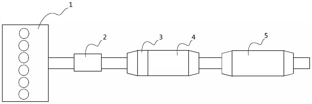
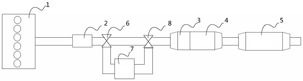
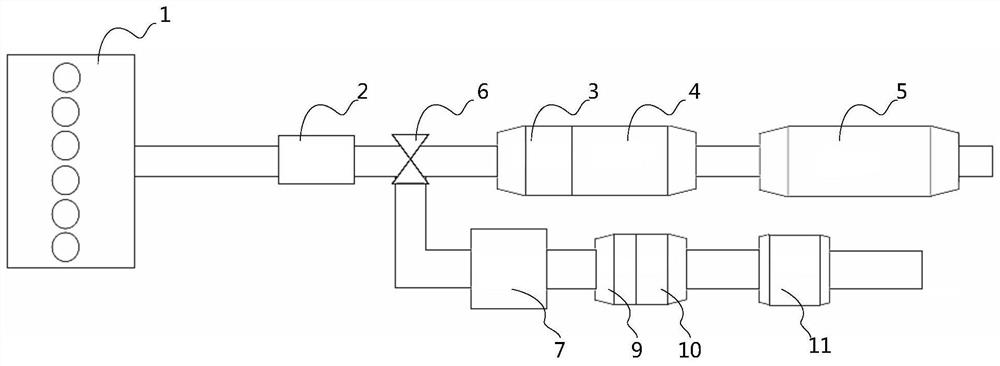
[0029] One of the cores of the present invention is to provide a desulfurization device for the aftertreatment system. The structure design of the desulfurization device for the aftertreatment system can avoid the poisoning of the aftertreatment device during the regeneration process of the regenerable sulfur trap and prolong the storage time. Sulfur trap replacement cycle.

[0030] Another core of the present invention is to provide a control method, a post-treatment system and a storage medium based on the desulfurization device of the above-mentioned after-treatment system.

[0031] The following will clearly and completely describe the technical solutions in the embodiments of the present invention with reference to the accompanying drawings in the embodiments of the present invention. Obviously, the described embodiments are only some, not all, embodiments of the present invention. Based on the embodiments of the present invention, all other embodiments obtained by person...


PUM


Abstract

The invention relates to a post-processing system and its desulfurization device, control method and storage medium. The desulfurization device includes a renewable sulfur trap, a storage sulfur trap and a first three-way valve. The renewable sulfur trap The filter and the first three-way valve are sequentially arranged upstream of the main post-processing device along the exhaust flow direction. The inlet of the first three-way valve is connected with the outlet of the regenerative sulfur trap, and the first outlet of the first three-way valve is connected with the main aftertreatment device. The inlet of the post-processing device is connected, the second outlet of the first three-way valve is connected with a bypass pipeline, and the storage type sulfur trap is installed in the bypass pipeline; the regeneration of the regenerable sulfur trap can be avoided through the above desulfurization device It does not need to prolong the regeneration interval of the regenerative sulfur trap, nor does it need to increase the volume of the regenerative sulfur trap. During non-regeneration, it does not affect the exhaust back pressure, but The storage sulfur trap is only used to capture the sulfur compounds released during the regeneration of the renewable sulfur trap, which has a long service life and does not need to be replaced frequently.

Description

technical field [0001] The invention relates to the technical field of engine aftertreatment, and in particular to an aftertreatment system, a desulfurization device, a control method and a storage medium thereof. Background technique [0002] Diesel engine aftertreatment system is prone to sulfur poisoning, which affects the adsorption of NOx, resulting in substandard emissions. In order to reduce the damage of sulfur dioxide, hydrogen sulfide, etc. to post-processing components, sulfur traps are generally installed upstream of post-processing devices, such as figure 1 As shown, the purpose is to remove sulfur compounds (H 2 S, SO 2 , SO 3 etc.), to improve the sulfur poisoning of post-treatment devices, and current sulfur traps generally include renewable sulfur traps and storage sulfur traps, among which, if figure 1 The scheme uses a renewable sulfur trap. Since the renewable sulfur trap needs to be regenerated regularly, the sulfides generated during the regeneratio...

Claims


Application Information

Patent Timeline
Patent Type & Authority Patents(China)
IPC IPC(8): F01N3/08F01N9/00F01N11/00F02D29/02
CPCF01N3/08F01N9/00F01N9/002F01N11/002F02D29/02F01N2570/04Y02T10/40
Inventor 解同鹏杨金鹏
Owner WEICHAI POWER CO LTD
Why Eureka
Try Eureka