Pneumatic safety type pneumatic screw pump and using method thereof
A kind of screw pump, safe technology, applied in the direction of rotary piston type/oscillating piston type pump components, rotary piston type/oscillating piston type pump combination, pump, etc. Tight, inconvenient to adjust the flow rate of the liquid inlet pipe, etc., to reduce noise, reduce vibration, and prevent falling off.
- Summary
- Abstract
- Description
- Claims
- Application Information
AI Technical Summary
Problems solved by technology
Method used
Image
Examples
Embodiment 1
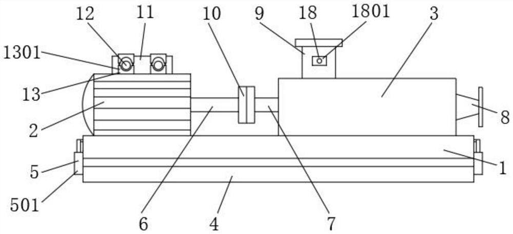
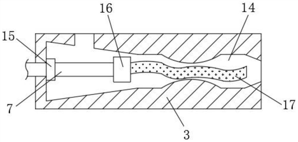
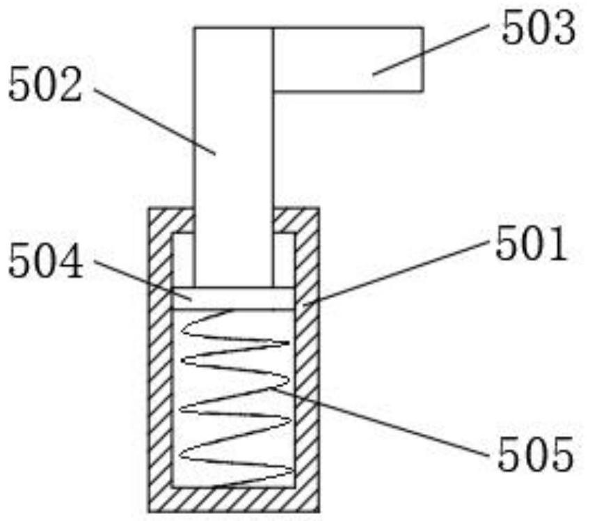
[0030] Such as Figure 1-5 As shown, the present invention relates to a pneumatically safe pneumatic screw pump, including a support base 1, an air motor 2 is fixedly installed on the upper surface of the support base 1 close to one side, and the upper surface of the support base 1 is fixed close to the other side The pump body casing 3 is installed, the base 4 is arranged under the support base 1, the shock absorbing mechanism 5 is connected between the base 4 and the support base 1, the output end of the air motor 2 is connected to a transmission shaft 6, and the pump body casing 3 One end is connected with the second transmission shaft 7, and the other end of the pump casing 3 is connected with a liquid outlet pipe 8, and the top of the pump casing 3 is connected with a liquid inlet pipe 9, between the first transmission shaft 6 and the second transmission shaft 7 A coupling 10 is connected, and the top of the air motor 2 is fixedly installed with an air connection seat 11,...
Embodiment 2
[0039] On the basis of Embodiment 1, a method for using a pneumatically safe pneumatic screw pump comprises the following steps:
[0040] S1: Connect the air pipe joint 12 to the air pipe, and connect the liquid inlet pipe 9 and the liquid outlet pipe 8 to the infusion pipe respectively;
[0041] S2: Pass the air pipe through the No. 1 tightening block 1301 and the No. 2 tightening block 1302 to connect with the air seat 11. The No. 2 tightening block 1302 is relatively movable through the connecting column 1303, the anti-drop joint 1304 and the return spring 1305. The air pipe is clamped;
[0042] S3: The air motor 2 starts to work, the air motor 2 drives the No. 1 transmission shaft 6 to rotate, the No. 1 transmission shaft 6 rotates through the coupling 10 to drive the No. 2 transmission shaft 7 to rotate, and the No. 2 transmission shaft 7 rotates through the universal joint 16 The feeding screw 17 is driven to rotate, and the feed liquid is delivered to the feeding chamb...
PUM
 Abstract
Description
Claims
Application Information
 - R&D
- Intellectual Property
- Life Sciences
- Materials
- Tech Scout
- Unparalleled Data Quality
- Higher Quality Content
- 60% Fewer Hallucinations
Browse by: Latest US Patents, China's latest patents, Technical Efficacy Thesaurus, Application Domain, Technology Topic, Popular Technical Reports.
© 2025 PatSnap. All rights reserved.Legal|Privacy policy|Modern Slavery Act Transparency Statement|Sitemap|About US| Contact US: help@patsnap.com


