
Piston ring circumference radial elastic force dynamic testing device

A technology for dynamic testing and piston rings, applied in measuring devices, elastic testing, force/torque/power measuring instruments, etc., can solve the problems of large measurement errors, low detection efficiency, low repeatability, etc., to reduce measurement errors, The effect of improving measurement accuracy and easy processing and manufacturing

Active Publication Date: 2021-07-13
JILIN UNIV
View PDF9 Cites 0 Cited by
  • Summary
  • Abstract
  • Description
  • Claims
  • Application Information

AI Technical Summary

Problems solved by technology

[0007] The detection of the radial elasticity of the existing piston rings is performed manually with artificial aids. There are problems of poor fixation and low repeatability during the detection. In the prior art, it is impossible to measure the radial elasticity of the piston ring at multiple points simultaneously. The efficiency is low, the measurement state cannot be the same as the force state of the piston ring when it is working, resulting in a large measurement error, and there is a problem of high cost of the detection device, so it is necessary to develop a dynamic test device for radial elastic force of the piston ring circumference

Method used


Image

  • Piston ring circumference radial elastic force dynamic testing device
  • Piston ring circumference radial elastic force dynamic testing device
  • Piston ring circumference radial elastic force dynamic testing device

Examples


specific Embodiment approach

[0046] Specific implementation method: adjust the first adjusting screw 16 to ensure that the first load cell 17 displays an extremely small value, adjust the second adjusting screw 19 to ensure that the second load cell 18 displays and its small value, and ensure that the two sensors and the floating measuring block 20 contact, and then install the piston-piston ring device into the cylinder 22, the floating measuring block 20 is in contact with the piston ring 2, observe the values ​​of the first load cell 17 and the second load cell 18 at this time, the difference between the two display values and is the radial elastic force value at this point in the circumferential direction of the piston ring 2. If the value is within the reasonable range of the radial elastic force of the piston ring 2, it means that when the piston ring 2 is static and installed in the working position, the force is more reasonable. The design of the ring 2 type line is preliminarily judged to be reaso...


PUM


Abstract

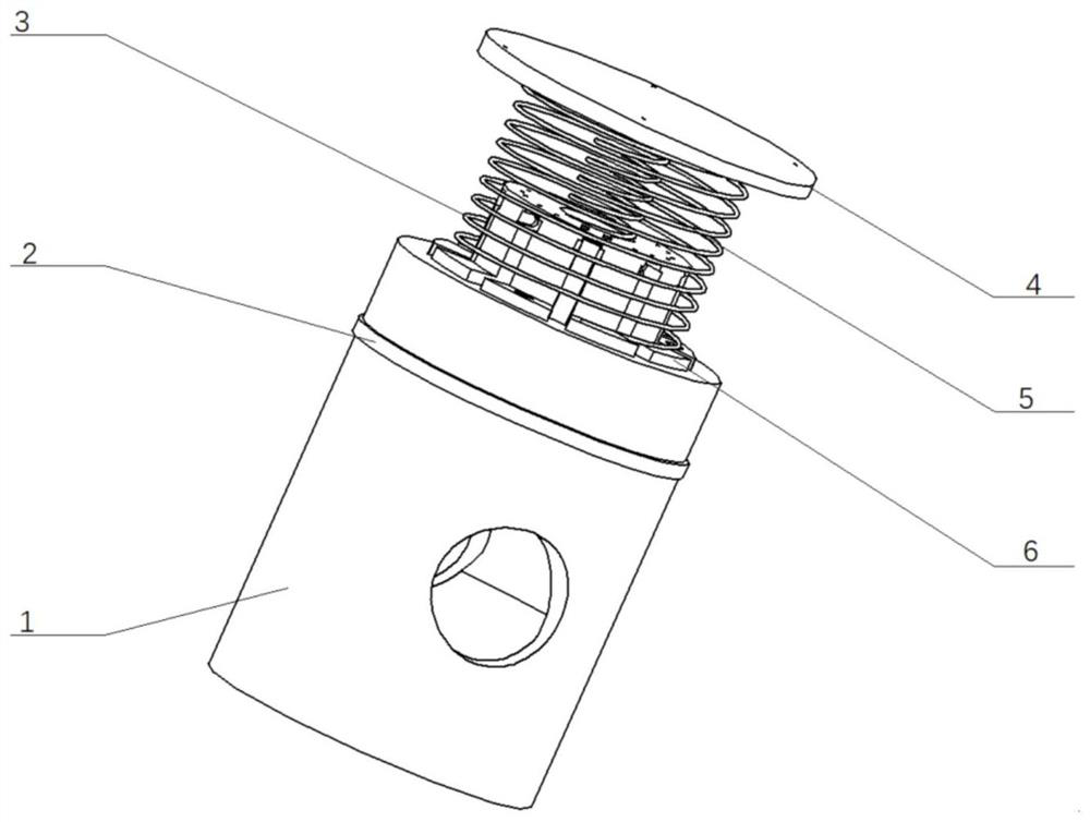
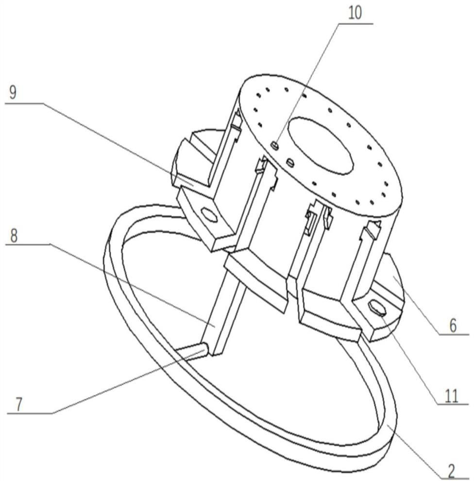
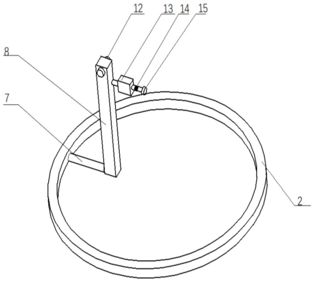
The invention belongs to the technical field of piston ring molded line design, and particularly relates to a piston ring circumference radial elastic force dynamic testing device which comprises a fixing component composed of a piston and an air cylinder, a force application component composed of a first spring and a second spring, and a measuring component divided into a piston ring circumferential radial elastic force static measuring component and a piston ring circumferential radial elastic force dynamic measuring component. The device is easy to machine and manufacture, the principle is simple, and the cost of all parts is low; during detection, the piston ring is installed in the ring groove to ensure the stability of the piston ring during detection. In the measurement process, the lever principle is utilized, the measured pressure value in the piston ring is amplified, measurement errors caused by the precision problem of the sensor are reduced, and the pin shaft and the lever are in spherical contact, so that the measurement precision can be improved; the stress state and the working state of the piston ring can be consistent in the measurement process, and the measurement precision is improved; and radial elastic force values at multiple points when the piston ring works under a dynamic condition can be simultaneously measured.

Description

technical field [0001] The invention relates to the technical field of piston ring profile design, in particular to a dynamic testing device for radial elastic force of the piston ring circumference. Background technique [0002] Piston rings are used in mechanical devices such as internal combustion engines, compressors, and hydraulic pressure, and mainly play the role of sealing and lubrication. [0003] The piston ring is embedded in the piston ring groove in the working state. According to the device where the piston ring is installed, it can be roughly divided into two types: compression ring and oil ring. [0004] Compression rings are used to seal high-pressure gas or high-pressure oil, and oil rings are used to scrape excess oil from the cylinder wall. The piston ring is non-circular in the free state, and its outer dimension is larger than the diameter of the cylinder. When the piston ring is installed in the cylinder, it is affected by its own radial elastic force...

Claims


Application Information

Patent Timeline
IPC IPC(8): G01L5/00G01M5/00
CPCG01L5/00G01M5/005
Inventor 苏醒马家义李雪松王忠恕李盛成
Owner JILIN UNIV
Learn More