Charging control circuit capable of realizing simultaneous charging and independent charging of double battery packs

A charging control, dual-battery technology, applied in secondary battery charging/discharging, battery disconnect circuit, battery circuit device, etc., can solve the problems of charging smoke and fire, unknown output level, direct connection, etc., to achieve high reliability , the effect of simple control logic

Pending Publication Date: 2021-07-13
深圳市誉娇诚科技有限公司
View PDF0 Cites 0 Cited by
  • Summary
  • Abstract
  • Description
  • Claims
  • Application Information

AI Technical Summary

Problems solved by technology

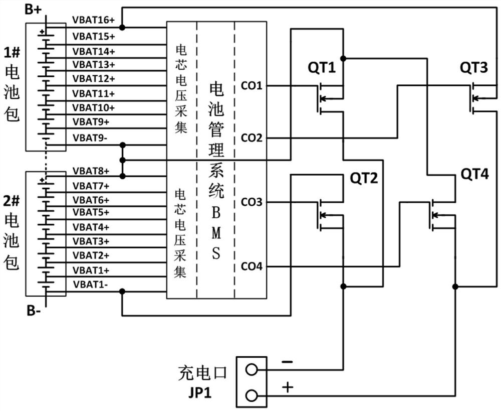
[0018] figure 1 Although the charging control circuit shown can realize the series charging of two battery packs and separate power supply, the control logic timing requirements for the charging control switches QT1~QT4 are very strict. If the MOS transistors QT3 and QT4 are closed simultaneously during the control process If the 1# battery pack will be directly short-circuited; if the MOS transistors QT1 and QT2 are closed at the same time during the control process, then the 2# battery pack will be directly short-circuited, which will inevitably cause the charging control circuit to burn out instantly.
The input and output (I / O) pins of the microprocessor (CPU) in the battery management system BMS will have unknown or uncertain output levels in the power-on, bootloader (Bootloader) and reset (Reset) modes. At this time, it is easy to have the phenomenon that the upper and lower bridge arms of QT1 / QT2 or QT3 / QT4 are directly connected. In severe cases, it may cause safety accidents such as charging smoke and fire.
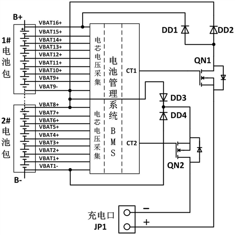
[0019] figure 2 The charging control circuit shown has two reverse current diodes on the charging circuit of each battery pack. Because of the tube voltage drop, a large heat loss will be generated during charging, and the charging efficiency is low. At the same time, two diodes cannot be realized. Separate charging of battery pack

Method used


Image

  • Charging control circuit capable of realizing simultaneous charging and independent charging of double battery packs
  • Charging control circuit capable of realizing simultaneous charging and independent charging of double battery packs
  • Charging control circuit capable of realizing simultaneous charging and independent charging of double battery packs

Examples


Embodiment Construction

[0037] The technical solutions in the embodiments of the present invention will be clearly and completely described below with reference to the accompanying drawings in the embodiments of the present invention. Obviously, the described embodiments are only a part of the embodiments of the present invention, not all of the embodiments. Based on the embodiments of the present invention, all other embodiments obtained by those of ordinary skill in the art without creative efforts shall fall within the protection scope of the present invention.

[0038] It should be noted that all directional indications (such as up, down, left, right, front, back, etc.) in the embodiments of the present invention are only used to explain the relationship between various components under a certain posture (as shown in the accompanying drawings). The relative positional relationship, the movement situation, etc., if the specific posture changes, the directional indication also changes accordingly. ...


PUM


Abstract

The invention relates to the technical field of charging of low-speed electric vehicles, discloses a charging control circuit capable of realizing simultaneous charging and independent charging of double battery packs, and provides a charging control circuit capable of realizing simultaneous charging and independent charging of double battery packs aiming at the defects of several charging control circuits of current low-speed electric vehicles. The control logic is simple, the reliability is high, the two battery packs can be charged at the same time when the voltage and the capacity of the two battery packs are insufficient, the consistency of the voltage and the capacity can be achieved in an independent charging mode when the voltage and the capacity of the two battery packs are not matched, the control logic is simple, and the reliability is high; favorable conditions are created for series-parallel operation of the vehicle-mounted battery pack, and the vehicle-mounted battery pack connecting device has a higher application value.

Description

technical field [0001] The invention relates to the technical field of low-speed electric vehicle charging, in particular to a charging control circuit capable of simultaneously charging two battery packs and separately replenishing power. Background technique [0002] At this stage, low-speed electric vehicles represented by old-age scooters have occupied a large market share in third- and fourth-tier cities, small towns and villages by virtue of their advantages such as affordable price, dexterity and convenience, practicality and easy maintenance. In addition, such as Low-speed electric vehicles for golf carts, police patrol cars, scenic sightseeing cars, etc. The initial tens of thousands of units have grown to millions of units in annual sales. [0003] Consumers of low-speed electric vehicles generally have low income and do not enjoy state subsidies, so they are not in the same breath as new energy electric vehicles (subsidized vehicles) in terms of safety technical ...

Claims


Application Information

Patent Timeline
Patent Type & Authority Applications(China)
IPC IPC(8): H02J7/00H01M10/42H01M10/44
CPCH01M10/4257H01M10/441H01M2010/4271H02J7/0014H02J7/0029H02J7/0031H02J7/007182Y02E60/10
Inventor 彭建华潘继雄周幼华
Owner 深圳市誉娇诚科技有限公司
Why Eureka
Try Eureka