Supercharge Your Innovation With Domain-Expert AI Agents!

Intelligent lock delay circuit

A delay circuit and smart lock technology, applied in the field of smart locks, can solve problems such as too many devices, software cannot be reset, downtime, etc., and achieve the effect of low cost

Active Publication Date: 2021-07-13
深圳市芯联信息技术有限公司
View PDF6 Cites 0 Cited by
  • Summary
  • Abstract
  • Description
  • Claims
  • Application Information

AI Technical Summary

Problems solved by technology

[0003] Generally, smart locks will inevitably have system abnormalities or downtime caused by the software system. Generally, this phenomenon cannot be reset by the software itself, and the circuit of the traditional smart lock is more complicated, with many devices and delays. Time length is not accurate

Method used


Image

  • Intelligent lock delay circuit

Examples


Embodiment Construction

[0023] The present invention will be described in detail below in conjunction with the accompanying drawings and specific embodiments. Obviously, the described embodiments are only a part of the embodiments of the application, not all of them. Based on the embodiments of the application, those of ordinary skill in the art All other embodiments obtained under the premise of no creative work belong to the scope of protection of this application.

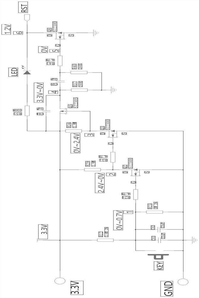
[0024] In this embodiment, the intelligent lock delay circuit of the present invention is as follows: figure 1 , including a key physical switch at the positive end and a reset switch at the negative pole, the circuit uses a voltage of 3.3V, a resistor R12 is connected to the positive pole, and the resistor R12 is connected in parallel with a capacitor C83, a capacitor C82 and a resistor R23, and the connection of the resistor R12 is Resistor R24, the resistor R24 ​​is connected to an NMOS transistor Q2, the NMOS transistor Q2 is conne...


PUM


Abstract

The invention relates to the technical field of intelligent locks, in particular to an intelligent lock delay circuit. The circuit comprises a key entity switch arranged at the positive electrode end and a reset switch arranged at the negative electrode; a 3.3 V voltage is adopted in the circuit, a resistor R12 is connected to the positive electrode, a capacitor C83, a capacitor C82 and a resistor R23 are connected to the resistor R12 in parallel, a resistor R24 is connected to the resistor R12, an NMOS tube Q2 is connected to the resistor R24, the NMOS tube Q2 is connected with a resistor R29 and a resistor R31 which are mutually connected in parallel, the resistor R31 is connected with an NMOS tube Q3, an output end of the NMOS tube Q3 is connected with a resistor R34 and an NMOS tube Q5 which are mutually connected in parallel, output ends of the resistor R34 and the NMOS tube Q5 which are mutually connected in parallel are connected with a capacitor C84 and a resistor R51, the resistor R51 is connected with an LED lamp, an output end of the LED lamp is connected with a reset switch, an output end of the capacitor C84 is connected with a capacitor C85, and the capacitor C85 is connected in parallel with a resistor R37 and a resistor R40 which are connected in parallel with each other. The circuit is low in cost, safe and stable, and the intelligent lock system can be reset through the circuit when the software function is abnormal.

Description

technical field [0001] The invention relates to the technical field of intelligent locks, in particular to an intelligent lock delay circuit. Background technique [0002] Smart door lock refers to a lock that is improved on the basis of being different from traditional mechanical locks, and is more intelligent and simple in terms of user security, identification, and management. The smart door lock is the executive component for locking the door in the access control system. Different from traditional mechanical locks, smart door locks are composite locks with safety, convenience and advanced technology. Magnetic card, radio frequency card (non-contact type, high security, plastic material, easy to configure and carry, low price) using non-mechanical key as a mature technology for user identification ID, such as: fingerprint lock, iris recognition access control (biometric identification, High security, no loss or damage; but inconvenient to configure, high cost) TM card ...

Claims


Application Information

Patent Timeline
Patent Type & Authority Applications(China)
IPC IPC(8): H03K17/28
CPCH03K17/28Y02B20/40
Inventor 黄斌邹春友
Owner 深圳市芯联信息技术有限公司
Features
  • R&D
  • Intellectual Property
  • Life Sciences
  • Materials
  • Tech Scout
  • Unparalleled Data Quality
  • Higher Quality Content
  • 60% Fewer Hallucinations
Learn More