Mechanical arm

A technology of manipulators and tracks, applied in the field of manipulators, can solve the problems of manipulator loss, loss of manipulator precision function, affecting stop performance, etc., to achieve the effect of improving accuracy, ensuring accuracy and reducing wear

Pending Publication Date: 2021-07-16
SHANGHAI MARITIME UNIVERSITY
View PDF0 Cites 0 Cited by
  • Summary
  • Abstract
  • Description
  • Claims
  • Application Information

AI Technical Summary

Problems solved by technology

[0003] Industrial manipulators generally move back and forth through rails. However, when the existing sliding rails need to move, in order to reduce friction, the inner wall is coated with organic oil. Therefore, when moving to the target range, it is necessary to stop the motion at the bottom of the manipulator by braking. Inertia, and the braking method is generally a brake or mechanical lock structure, which will not only affect its stopping performance under long-term use, but the manipulator as a precision device will also form a certain loss under the action of inertia, thus losing the original performance of the manipulator. precision function

Method used


Image

  • Mechanical arm
  • Mechanical arm
  • Mechanical arm

Examples


Embodiment 1

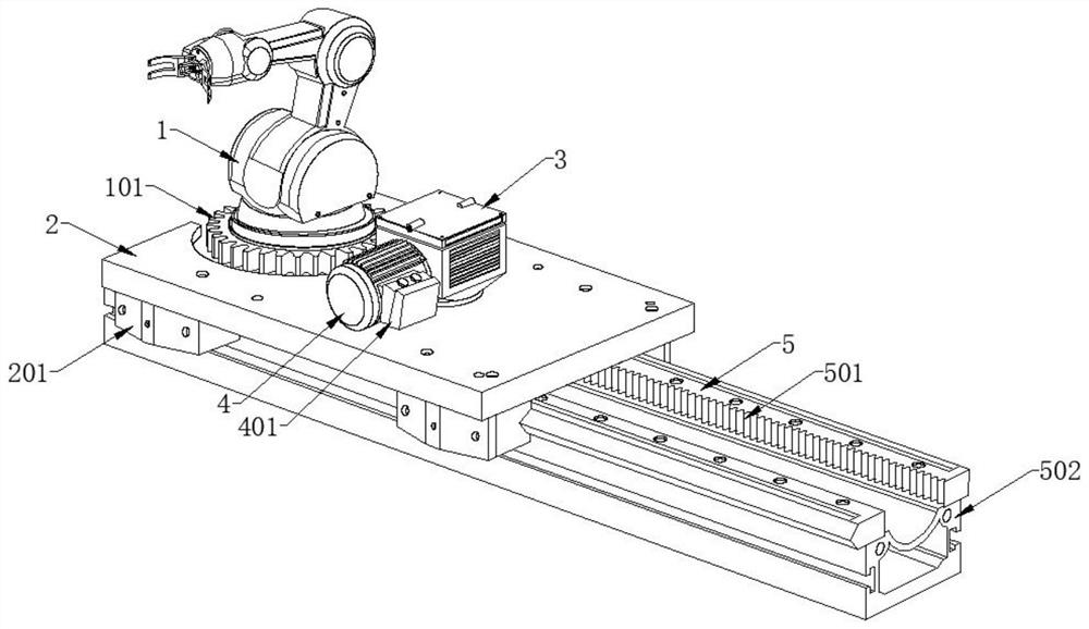
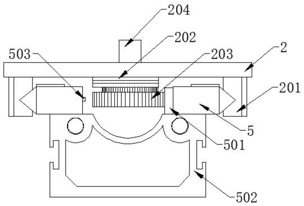
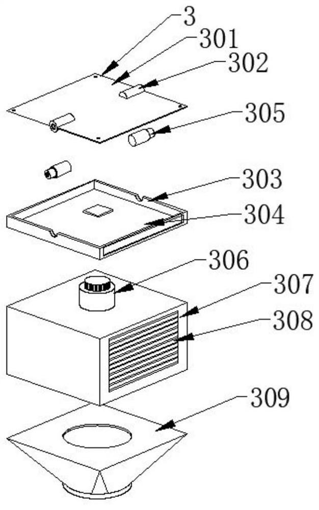
[0028] Such as Figure 1-5 As shown, the present invention provides a kind of manipulator, comprises manipulator 1, rail base 502 and cogged groove track 5, and the bottom end of manipulator 1 is equipped with toothed plate 101, and the bottom end of toothed plate 101 is equipped with placing platform 2, and the bottom of placing platform 2 A control module 3 is installed in the middle of the surface, a driving motor 4 is installed at one end of the control module 3, a mechanical control switch 401 is installed at one end of the driving motor 4, a sliding block 201 is installed on both sides of the bottom end of the placing platform 2, and the inner side of the sliding block 201 A cogged track 5 is installed, a notch 501 is arranged on one side of the cogged track 5, a track base 502 is installed at the bottom of the cogged track 5, a cover plate 301 is installed on the top of the control module 3, and the surface of the cover plate 301 Both ends are provided with a protective...


PUM


Abstract

The invention discloses a mechanical arm. The mechanical arm comprises a mechanical arm body, track bases and tooth groove tracks, a fluted disc is installed at the bottom end of the mechanical arm body, a containing platform is installed at the bottom end of the fluted disc, a control module is installed in the middle of the surface of the containing platform, a driving motor is installed at one end of the control module, and a mechanical control switch is installed at one end of the driving motor; sliding blocks are installed on the two sides of the bottom end of the containing platform, the tooth groove tracks are installed on the inner sides of the sliding blocks, notches are formed in the inner walls of one sides of the tooth groove tracks, and the track bases are installed at the bottom ends of the tooth groove tracks. An object capturing instrument capable of capturing the target distance is arranged, the mechanical arm body and the tooth groove tracks are combined, the distance between the mechanical arm and an target object can be captured in real time in the moving process, the mechanical arm can accurately stop on the vertical line of the target object after calculation according to the distance, and the accuracy of the mechanical arm in a practical process is ensured.

Description

technical field [0001] The invention relates to the field of manipulators, in particular to a manipulator. Background technique [0002] The manipulator is the most widely used automatic mechanical device in the field of robot technology. It can be seen in the fields of industrial manufacturing, medical treatment, entertainment services, military, semiconductor manufacturing, and space exploration. Although their shapes are different, they all have a common feature, that is, they can accept instructions and precisely locate a certain point in three-dimensional (or two-dimensional) space for operation. [0003] Industrial manipulators generally move back and forth through rails. However, when the existing sliding rails need to move, in order to reduce friction, the inner wall is coated with organic oil. Therefore, when moving to the target range, it is necessary to stop the motion at the bottom of the manipulator by braking. Inertia, and the braking method is generally a bra...

Claims


Application Information

Patent Timeline
Patent Type & Authority Applications(China)
IPC IPC(8): B25J5/02B25J9/12B25J9/16
CPCB25J5/02B25J9/1035B25J9/123B25J9/1602B25J9/1694
Inventor 梅潇郭泽鑫徐全旺
Owner SHANGHAI MARITIME UNIVERSITY
Why Eureka
Try Eureka