Electromechanical braking control system

A brake control and electro-mechanical technology, applied in the directions of brakes, brake transmissions, transportation and packaging, can solve the problems of slow response and low control accuracy, and achieve the effect of high-precision response and high-precision control

Active Publication Date: 2021-07-16
TRAFFIC CONTROL TECH CO LTD
View PDF7 Cites 1 Cited by
  • Summary
  • Abstract
  • Description
  • Claims
  • Application Information

AI Technical Summary

Problems solved by technology

[0005] The invention provides an electromechanical brake control system, which is used to solve the defects of low control precision and slow response caused by air brake in the prior art

Method used


Image

  • Electromechanical braking control system
  • Electromechanical braking control system

Examples


Embodiment Construction

[0027] In order to make the purpose, technical solutions and advantages of the present invention clearer, the technical solutions in the present invention will be clearly and completely described below in conjunction with the accompanying drawings in the present invention. Obviously, the described embodiments are part of the embodiments of the present invention , but not all examples. Based on the embodiments of the present invention, all other embodiments obtained by persons of ordinary skill in the art without creative efforts fall within the protection scope of the present invention.

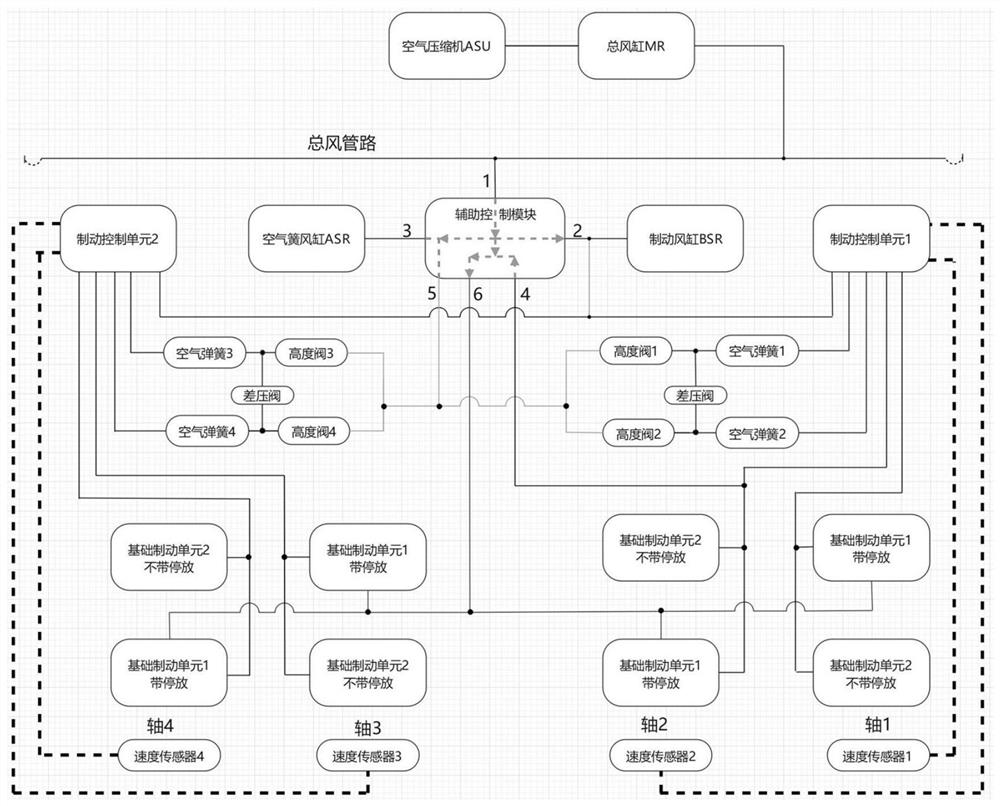
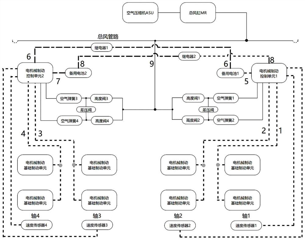
[0028] Aiming at the deficiencies in the prior art, the present invention proposes an electromechanical braking control system based on ATO (Automatic Train Operation, automatic train driving system) and TCMS control fusion, figure 2 It is the realization schematic diagram of the EMB braking system provided by the present invention, as figure 2 shown, including:

[0029] Air compressor, t...


PUM


Abstract

The invention provides an electromechanical braking control system. The electromechanical braking control system comprises an air compressor, a main air reservoir, an electromechanical braking control unit, an electromechanical braking basic braking unit, a height valve, a differential pressure valve, an air spring and a speed sensor. The air compressor, the main air reservoir, the height valve, the differential pressure valve, the air spring and the electromechanical braking control unit are sequentially connected through air pipelines. The electromechanical braking control unit is electrically connected with the electromechanical braking basic braking unit and the speed sensor. The electromechanical braking control system is controlled and managed by the integrated fusion control platform. The brake control system suitable for the EMB system is designed on the basis of the EMB system, communication with an integrated platform integrating ATO and TCMS control is achieved, output of friction brake force is completed, high-precision response and high-precision control of whole vehicle brake are achieved, and virtual connection and virtual marshalling of vehicles are achieved.

Description

technical field [0001] The invention relates to the technical field of train braking, in particular to an electromechanical braking control system. Background technique [0002] In the rail vehicle air brake system, the brake system is mainly composed of typical equipment and air pipeline connections, in which the speed information of each axis is transmitted to the brake control unit through the speed sensor, and based on the speed information, The brake control unit performs anti-skid control, and the overall structure is as follows: figure 1 shown. [0003] However, in some existing schemes using electromechanical braking systems, the specific control logic and communication with TCMS (Train Control and Management System) and TCU (Traction Control Unit, traction control unit) are still Execute according to the current mainstream scheme, that is, the BCU (Brake Control Unit, brake control unit) distributes the braking force according to the principle of braking force dis...

Claims


Application Information

Patent Timeline
IPC IPC(8): B60T13/74
CPCB60T13/74B60T13/746
Inventor 陈旭
Owner TRAFFIC CONTROL TECH CO LTD
Why Eureka
Try Eureka