
Precise assembling and adjusting device for steel truss girder and assembling construction method

An adjustment device, a technology of steel truss girder, applied in the direction of bridge, truss bridge, bridge construction, etc., can solve the problems of collision, gap, dislocation, great influence of vertical roof installation, unable to effectively ensure the assembly accuracy of steel truss girder, etc. Achieve the effect of avoiding offset, high rectification accuracy, and guaranteed height

Active Publication Date: 2021-07-16
南通帆森能源科技有限公司
View PDF11 Cites 0 Cited by
  • Summary
  • Abstract
  • Description
  • Claims
  • Application Information

AI Technical Summary

Problems solved by technology

[0004] However, in the above-mentioned patent, only the longitudinal positions of the adjacent two upper chords are limited to ensure the same height, thereby improving the accuracy of assembly, but when the beam section to be assembled slides to the beam section that has been assembled, it is inevitable that the beam section to be assembled will appear. The lateral offset of the axis of the beam section, and the lateral offset of the beam section to be assembled has a great influence on the vertical jacking, horizontal continuous jacking force and installation after the jacking is in place when the steel truss beam section is assembled. If the offset of the beam segment to be assembled when sliding laterally is avoided, the assembly accuracy of the steel truss girder cannot be effectively guaranteed. Once a very small deviation occurs, collisions, gaps, dislocations, etc. may appear at the joint of the splicing rods of the two assembled beam segments Phenomenon

Method used


Image

  • Precise assembling and adjusting device for steel truss girder and assembling construction method
  • Precise assembling and adjusting device for steel truss girder and assembling construction method
  • Precise assembling and adjusting device for steel truss girder and assembling construction method

Examples


Embodiment Construction

[0043] In order to deepen the understanding of the present invention, the present invention will be further described below in conjunction with the embodiments and accompanying drawings. The embodiments are only used to explain the present invention and do not constitute a limitation to the protection scope of the present invention.

[0044] In the description of the present invention, it should be understood that the terms indicating orientation or positional relationship, such as based on the orientation or positional relationship shown in the drawings, are only for the convenience of describing the present invention and simplifying the description, rather than indicating or implying the Structures or units must have a specific orientation and thus should not be construed as limiting the invention.

[0045] In the present invention, unless otherwise clearly specified and limited, terms such as "connected", "provided" and "had" should be understood in a broad sense, for exampl...


PUM


Abstract

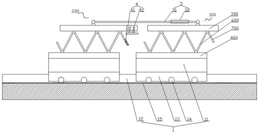
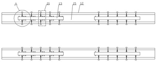
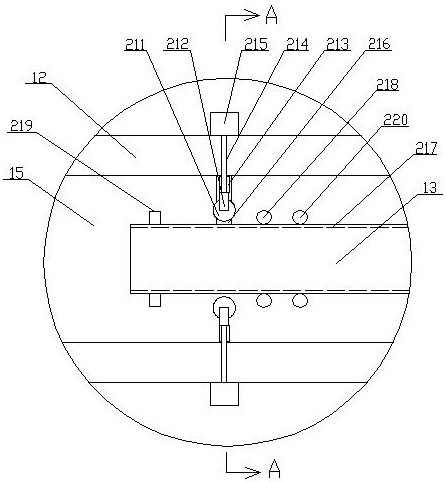
The invention relates to a precise assembling and adjusting device for a steel truss girder. The precise assembling and adjusting device comprises a sliding mechanism, a deviation rectifying mechanism which is arranged on the slide way and performs real-time deviation rectifying on the steel truss girder sections on the two sliding jig frames, and the deviation rectifying mechanism comprises a plurality of deviation rectifying roller assemblies arranged on the slide way and a control unit for adjusting and controlling the deviation rectifying roller assemblies; a dragging mechanism which drags and closes the to-be-assembled beam section towards the assembled beam section; and a positioning mechanism which comprises a node positioning assembly and an end point positioning assembly. The device has the following advantages that the straightness and height alignment of the to-be-assembled beam section sliding towards the assembled beam section are ensured by arranging the deviation rectifying mechanism, and then precise positioning between the two adjacent upper chords and between the two adjacent splicing rods is sequentially ensured through the end point positioning assemblies and the node positioning assemblies; therefore, accurate assembly of the steel truss girder sections is effectively guaranteed.

Description

Technical field: [0001] The invention belongs to the field of steel truss beam construction, and in particular relates to a steel truss beam precise assembly adjustment device and an assembly construction method. Background technique: [0002] The steel truss girder is the main structure to ensure the driving of the vehicle and improve the vertical rigidity of the structure. To give full play to the mechanical properties of the material, the steel truss girder has the characteristics that each internode member can flexibly change the steel type and section according to the magnitude of the force, showing good economic performance, soft outline, and majestic bridge shape. Reflect the style of modern industrialization. [0003] At present, when assembling steel truss girder segments, a temporary platform is set up in the assembly and docking area, and the position of the steel truss girder segments is adjusted by suspension of the crane. After the initial docking is completed...

Claims


Application Information

Patent Timeline
Patent Type & Authority Applications(China)
IPC IPC(8): E01D21/00E01D6/00E01D19/00
CPCE01D21/00E01D6/00E01D19/00
Inventor 刘红梅李建炎方荣光牛红飞曹华任茂明
Owner 南通帆森能源科技有限公司
Learn More