Bearing retainer

A technology of bearing cages and cages, which is applied in the direction of bearing components, shafts, bearings, bearing cooling, etc., can solve the problems of heat dissipation due to frictional heat between rolling elements and cages, and improve heat dissipation performance Effect

Inactive Publication Date: 2021-07-16
洛阳德润精密机床轴承有限公司
View PDF6 Cites 2 Cited by
  • Summary
  • Abstract
  • Description
  • Claims
  • Application Information

AI Technical Summary

Problems solved by technology

The cage is used to separate two adjacent rolling elements, so that multiple rolling elements can be evenly distributed between the inner ring and the outer ring along the circumferential direction, so as to avoid collision and friction between two adjacent rolling

Method used


Image

  • Bearing retainer
  • Bearing retainer
  • Bearing retainer

Examples


Embodiment 1

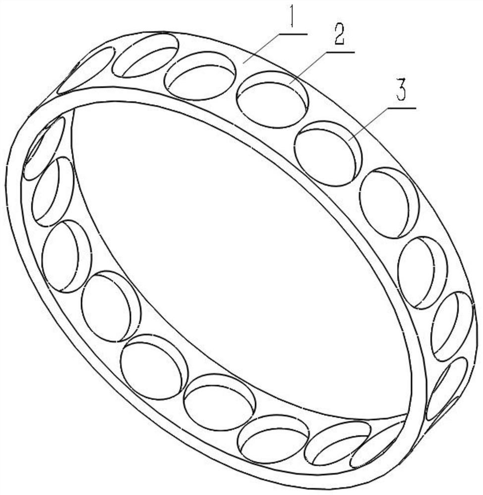
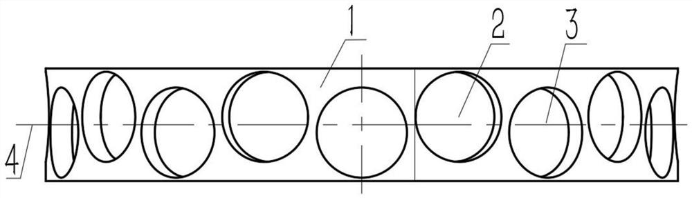
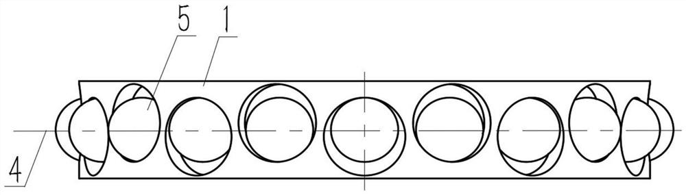
[0011] Such as figure 1 , figure 2 , image 3 As shown, the present invention discloses a bearing cage. The technical solution adopted is to include a cage body 1, and the cage body 1 is provided with an upper bias pocket 2 and a lower bias pocket for guiding the rolling elements 5. 3. The number of the upper partial pocket holes 2 and the lower partial pocket holes 3 is even in number and the intervals are evenly arranged.

[0012] The axial centerline 4 of the cage body 1 is at the same distance from both ends of the cage body 1 . The center of the upper eccentric pocket hole 2 is offset upward from the axial centerline 4, and the center of the lower eccentric pocket 3 is offset downward from the axial centerline 4. The offset distance is equal to the installed 2% of the length of the diameter of the rolling element 5.

[0013] Working principle of the present invention: the center of the upper partial pocket hole 2 and the lower partial pocket hole 3 designed by the pr...


PUM


Abstract

The invention discloses a bearing retainer. The bearing retainer comprises a retainer body, upward shifting pockets and downward shifting pockets. According to the bearing retainer, the positions of the pockets are shifted, and the centers of rolling bodies can still be in the same plane in the working process of a bearing, that is, the circle centers of the pockets coincide with the sphere centers of the rolling bodies, and the sphere centers of the rolling bodies are kept in the same plane, so that a large eccentric gap is formed between the rolling bodies and the retainer in the working process of the bearing, the heat dissipation performance of the bearing is improved, and the performance and the service life of the bearing are prevented from being influenced by overheating of the bearing.

Description

technical field [0001] The invention relates to the field of bearings, in particular to a bearing cage. Background technique [0002] Bearings are widely used in automotive and industrial fields. Bearings generally include inner rings, outer rings, cages and rolling elements. The rolling elements are arranged between the inner ring and the outer ring and can rotate to realize the relative rotation between the inner ring and the outer ring. The cage is used to separate two adjacent rolling elements, so that multiple rolling elements can be evenly distributed between the inner ring and the outer ring in the circumferential direction, so as to avoid collision and friction between two adjacent rolling elements. Both frames solve the problem of preventing two adjacent rolling elements from rubbing and colliding, but they do not solve the friction between the rolling elements and the cage and the problem of heat radiation generated by friction. Contents of the invention [00...

Claims


Application Information

Patent Timeline
IPC IPC(8): F16C33/38F16C37/00
CPCF16C33/38F16C37/00
Inventor 王彦成
Owner 洛阳德润精密机床轴承有限公司
Why Eureka
Try Eureka