Ball rotating shaft structure capable of converting degree of freedom and having dynamic balance

A technology of dynamic balance and rotating shaft structure, which is applied to mechanical equipment, supporting machines, machines/stands, etc., can solve the problems of inconvenience, only static positioning and shooting, and cannot adjust the left and right angles at will, and achieves easy operation and multiple angles. to improve the quality of the shot

Pending Publication Date: 2021-07-16
肖红
View PDF8 Cites 0 Cited by
  • Summary
  • Abstract
  • Description
  • Claims
  • Application Information

AI Technical Summary

Problems solved by technology

Most of the ball shafts of the ball heads used in the most common cameras and cameras can only be positioned statically for shooting, or the ball needs to be adjusted to a fixed position to align with the pin hole, and the pin is inserted into the ball hole to position and realize mobile shooting , it is very inconvenient to use, and when shooting vertically and horizontally, the

Method used


Image

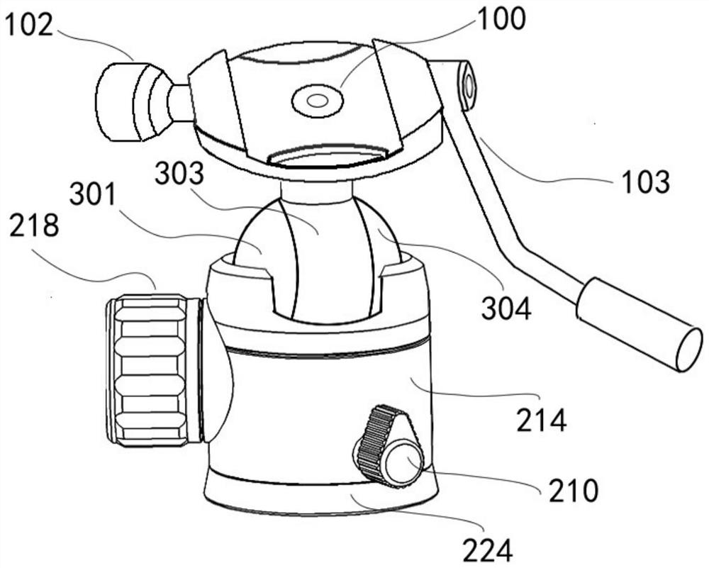
  • Ball rotating shaft structure capable of converting degree of freedom and having dynamic balance
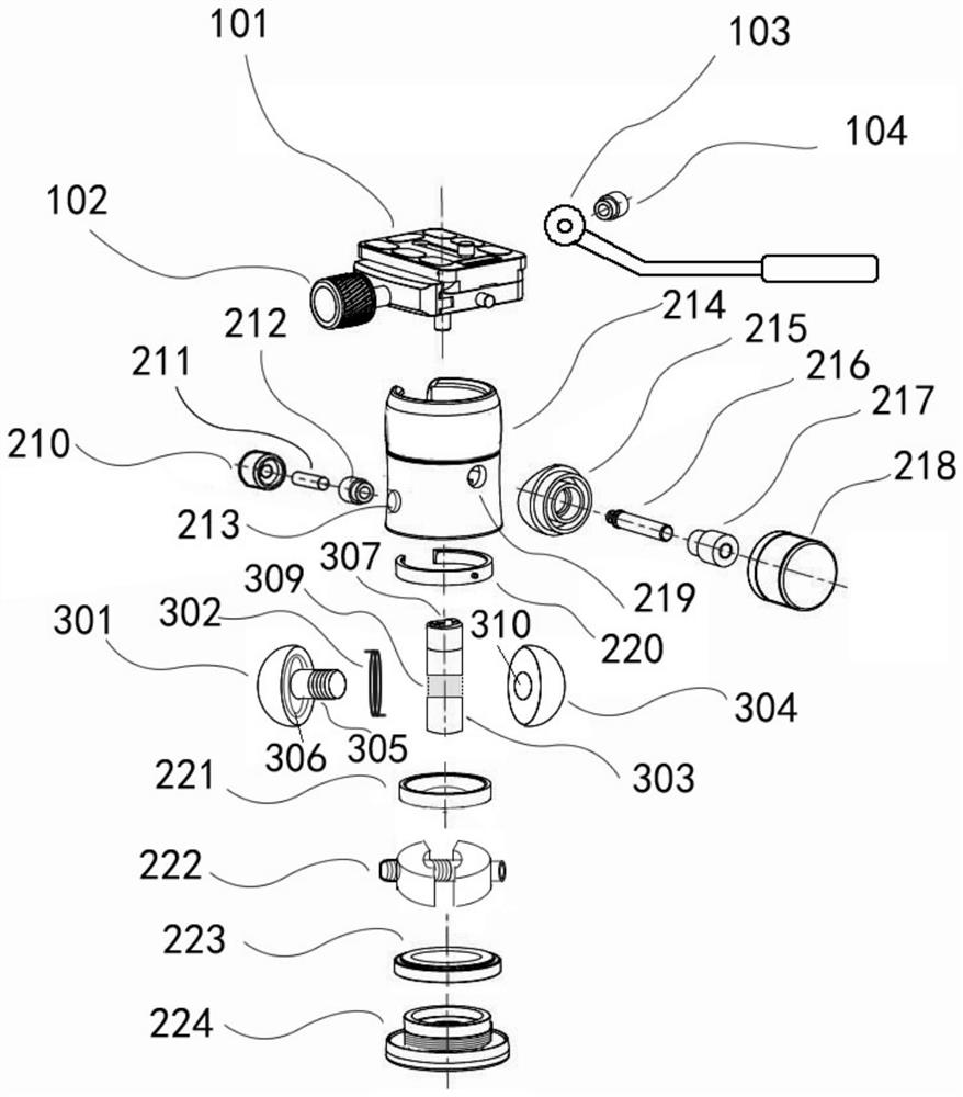
  • Ball rotating shaft structure capable of converting degree of freedom and having dynamic balance
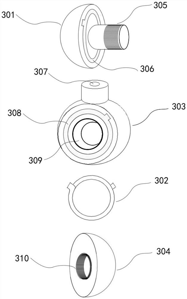
  • Ball rotating shaft structure capable of converting degree of freedom and having dynamic balance

Examples


Example Embodiment

[0019] Next, the technical solutions in the embodiments of the present invention will be described in contemplation in the embodiments of the present invention, and clearly, as described herein is merely, not all of the embodiments of the present invention. Based on the embodiments of the present invention, those of ordinary skill in the art will belong to the scope of the present invention without all other embodiments obtained without creative labor.

[0020] It should be noted that if there is a directional indication (such as above, lower, left, right, post, post, ...), the directional indication is only used to interpret a particular attitude (such as the figures) Sign) The relative positional relationship between the components, movement conditions, etc., if the specific posture changes, the directional indication is also changed accordingly.

[0021] Further, in the embodiment of the present invention relates to a description of "first", "second", the description of the "fi...


PUM


Abstract

The invention discloses a ball rotating shaft structure capable of converting the degree of freedom and having dynamic balance. A ball rotating shaft comprises an outer shell which can accommodate the ball rotating shaft to rotate in an inner cavity, a non-slip ring and an elastic push block; the ball rotating shaft is characterized by being divided into a left part, a middle part and a right part, the left part is provided with a torsional spring clamping groove and a convex shaft, the outer side of the middle part is provided with a torsional spring clamping groove and a round hole, the convex shaft of the left part can penetrate through the round hole to be fixedly connected with a screw hole of the right part, and then a complete spherical body can be formed and makes contact with the non-slip ring according to the principle that the areas of the left part and the right part are large, and the larger tightness degree range and the positioning effect are generated; as the area of the middle part is small, the effect of delaying resistance is achieved, movable shooting and dynamic balance operation can be carried out, when the middle part needs to be locked and fixed, the middle part can be locked and fixed by adjusting a locking push block knob, the two-degree-of-freedom and three-degree-of-freedom conversion of universal positioning mobile shooting and the dynamic balance effect are achieved, and the ball rotating shaft has the advantages of being easy to convert and convenient to operate.

Description

technical field [0001] The invention relates to the technical field of a ball rotating shaft, in particular to the technical field of two-degree-of-freedom and three-degree-of-freedom conversion and dynamic balance positioning. Background technique [0002] With the advent of the era of artificial intelligence, mechanical automation and robot arms, including electronic digital products, use ball-rotating shaft structures to achieve conversion, carrying, and movement in two-degree-of-freedom and three-degree-of-freedom spaces. Most of the ball shafts of the ball heads used in the most common cameras and cameras can only be positioned statically for shooting, or the ball needs to be adjusted to a fixed position to align with the pin hole, and the pin is inserted into the ball hole to position and realize mobile shooting , it is very inconvenient to use, and when shooting vertically and horizontally, the left and right angles cannot be adjusted at will. Therefore, it is neces...

Claims


Application Information

Patent Timeline
IPC IPC(8): F16M11/14F16M11/04F16M11/18
CPCF16M11/14F16M11/043F16M11/18
Inventor 肖红
Owner 肖红
Why Eureka
Try Eureka