Current detection circuit
A technology of current detection circuit and current detection resistor, which is applied in the direction of measuring current/voltage, only measuring current, measuring devices, etc., and can solve the problem of reducing the voltage value of the input terminal of the comparator
- Summary
- Abstract
- Description
- Claims
- Application Information
AI Technical Summary
Problems solved by technology
Method used
Image
Examples
Embodiment Construction
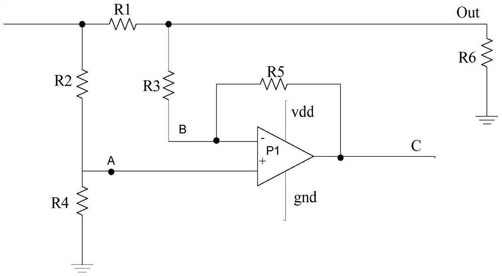
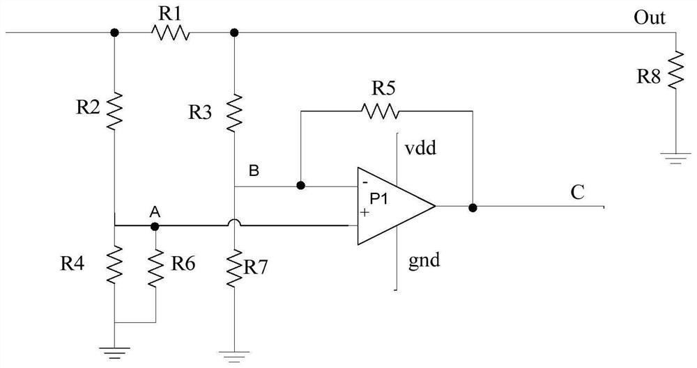
[0016] . figure 1 It is a typical current detection circuit, wherein, resistor R2=R3, resistor R4=R5. The current passes through the detection resistor R1, and a voltage difference ΔV is generated between the upper end of the resistor R4 and the upper end of the resistor R5. For an ideal op amp, the positive and negative inputs have approximately the same potential. Therefore, the current difference flowing through the resistors R1 and R2 is ΔI=ΔV / R11. This current difference will completely act on the resistors R4 and R5. Considering that the potentials at one end of the resistors R4 and R5 are the same, the voltage difference at the other end is: Because the other end of the resistor R4 is grounded. That is, the voltage is 0V, then under stable conditions, the other end of the resistor R5, that is, the output potential of the op amp is ΔV out ;
[0017] Thus ΔV out The magnitude of reflects the magnitude of the current flowing through the resistor R1 terminal, or the m...
PUM
 Abstract
Description
Claims
Application Information
 - R&D
- Intellectual Property
- Life Sciences
- Materials
- Tech Scout
- Unparalleled Data Quality
- Higher Quality Content
- 60% Fewer Hallucinations
Browse by: Latest US Patents, China's latest patents, Technical Efficacy Thesaurus, Application Domain, Technology Topic, Popular Technical Reports.
© 2025 PatSnap. All rights reserved.Legal|Privacy policy|Modern Slavery Act Transparency Statement|Sitemap|About US| Contact US: help@patsnap.com


