A cord-driven foldable umbrella antenna

A rope-driven, umbrella-shaped antenna technology, applied in the aerospace field, to achieve the effect of reducing the number of drives, compact antenna structure, and high motion accuracy

Active Publication Date: 2022-02-11
BEIJING INSTITUTE OF TECHNOLOGYGY
View PDF9 Cites 0 Cited by
  • Summary
  • Abstract
  • Description
  • Claims
  • Application Information

AI Technical Summary

Problems solved by technology

In order to save space in the non-working state and improve the transportation performance of curved antennas, many antenna reflectors are designed to be foldable, but the existing frame, solid surface, inflatable and peripheral truss antennas are all It is difficult to meet the requirements of high rigidity, high storage ratio, high precision and large diameter at the same time

Method used


Image

  • A cord-driven foldable umbrella antenna
  • A cord-driven foldable umbrella antenna
  • A cord-driven foldable umbrella antenna

Examples


Embodiment Construction

[0027] The present invention will be described in detail below with reference to the accompanying drawings and examples.

[0028] This embodiment provides a rope-driven foldable umbrella-shaped antenna, which can realize two-stage folding in the non-working state to save space and facilitate transportation; in the working state, the antenna can be resumed under the action of a spring; at the same time , the folding mechanism is also designed with a locking component for antenna deployment to ensure high rigidity after the antenna is deployed.

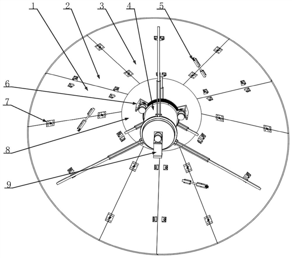
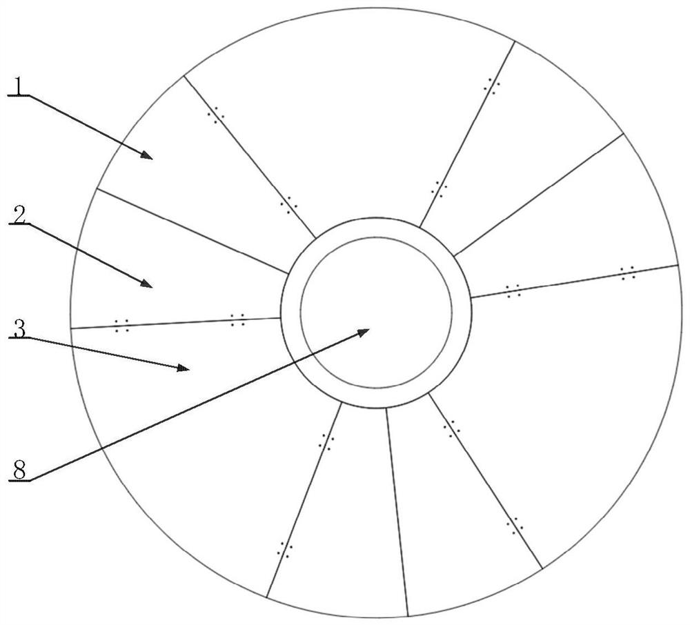
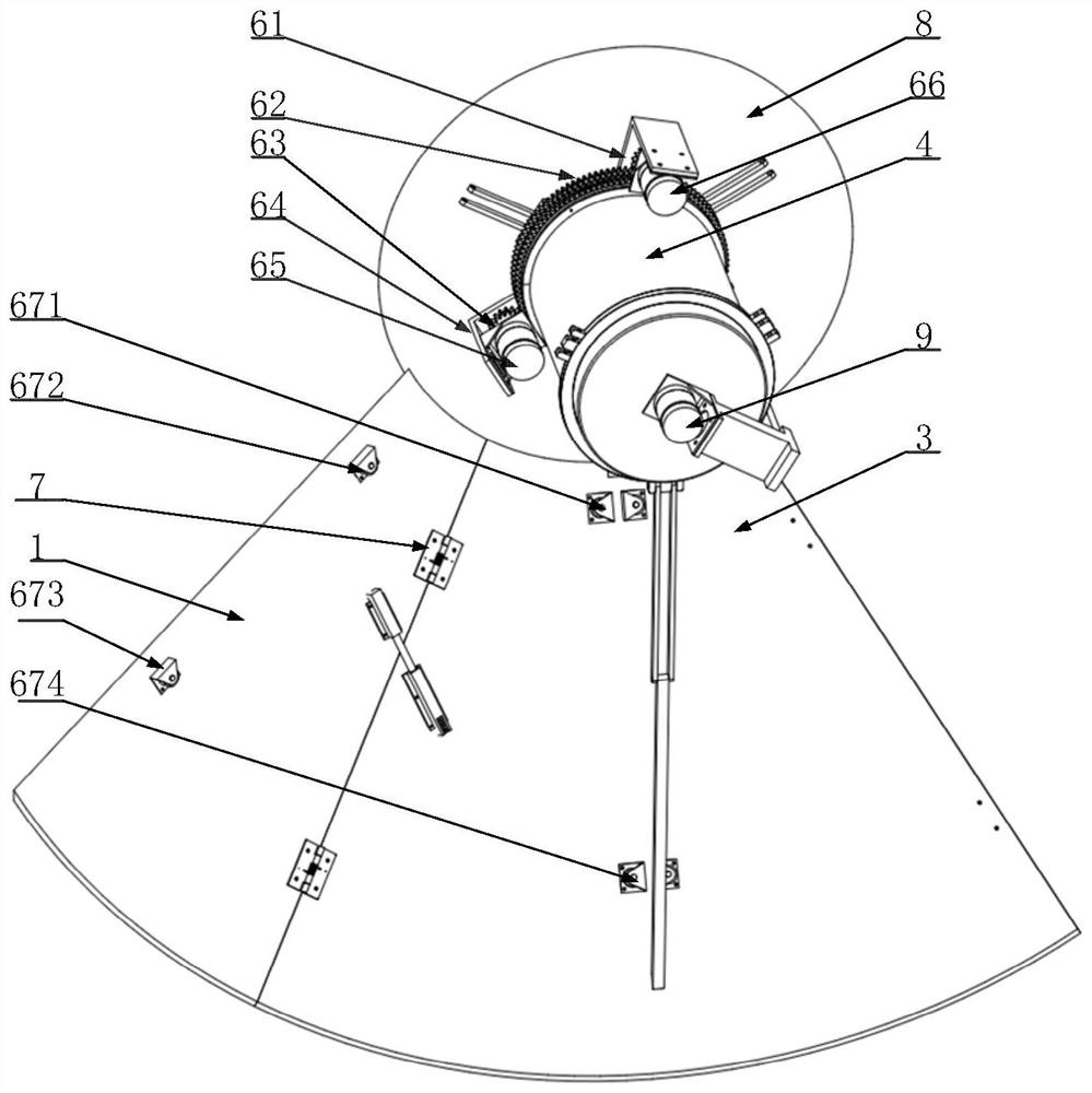
[0029] Such as figure 1 , figure 2 and Figure 6 As shown, the foldable umbrella-shaped antenna includes: a sector array, an intermediate column 4 , a locking component 5 , a rope driving component 6 , a ball head 8 and a link driving mechanism 9 .

[0030] The connection relationship of the foldable umbrella-shaped antenna is as follows: more than three sets of fan-shaped arrays are evenly distributed along a circumferential direct...


PUM


Abstract

The invention discloses a rope-driven foldable umbrella antenna, which relates to the field of aerospace technology and includes: a fan-shaped array, an intermediate column, a locking assembly, a rope driving assembly, a ball head and a connecting rod driving mechanism; three groups of the above-mentioned The sector arrays are evenly distributed along a circumferential direction of the ball head to form a foldable umbrella antenna. The middle column is in contact with the ball head. There is a link driving mechanism between the center column and each sector array, which can drive all sector arrays. Synchronous deployment or two-stage folding relative to the middle column; wherein, each fan-shaped array is provided with a locking assembly, and a rope driving assembly is provided between the locking assembly and the ball head. When the umbrella antenna is unfolded, the rope driving assembly drives the locking assembly to lock. When the umbrella antenna needs to be folded, the rope driving component drives the locking component to unlock, and each fan-shaped array can be folded one level along the circumferential direction.

Description

technical field [0001] The invention relates to the field of aerospace technology, in particular to a cable-driven foldable umbrella-shaped antenna. Background technique [0002] As a device used to effectively transmit and receive radio waves in radio systems such as broadcasting, television, navigation, radar and communications, antennas play an irreplaceable role in the aerospace field. For the radar with curved surface antenna, it will occupy a large spatial position in the unfolded state, which seriously restricts its maneuverability. In order to save space in the non-working state and improve the transportation performance of curved antennas, many antenna reflectors are designed to be foldable, but the existing frame, solid surface, inflatable and peripheral truss antennas are all It is difficult to meet the requirements of high rigidity, high storage ratio, high precision, and large diameter at the same time. In contrast, the umbrella-shaped deployable antenna has o...

Claims


Application Information

Patent Timeline
Patent Type & Authority Patents(China)
IPC IPC(8): H01Q1/08H01Q15/16
CPCH01Q1/08H01Q15/162
Inventor 赵杰亮吴祥兵王文中
Owner BEIJING INSTITUTE OF TECHNOLOGYGY
Why Eureka
Try Eureka