
A high-efficiency hot air cooking device

A cooking device and high-efficiency technology, applied in the field of kitchen utensils, can solve the problems of easy turbulence, affecting the taste of food cooking, and long heating time, so as to achieve the effect of improving cooking efficiency

Active Publication Date: 2022-02-01
JOYOUNG CO LTD
View PDF7 Cites 0 Cited by
  • Summary
  • Abstract
  • Description
  • Claims
  • Application Information

AI Technical Summary

Problems solved by technology

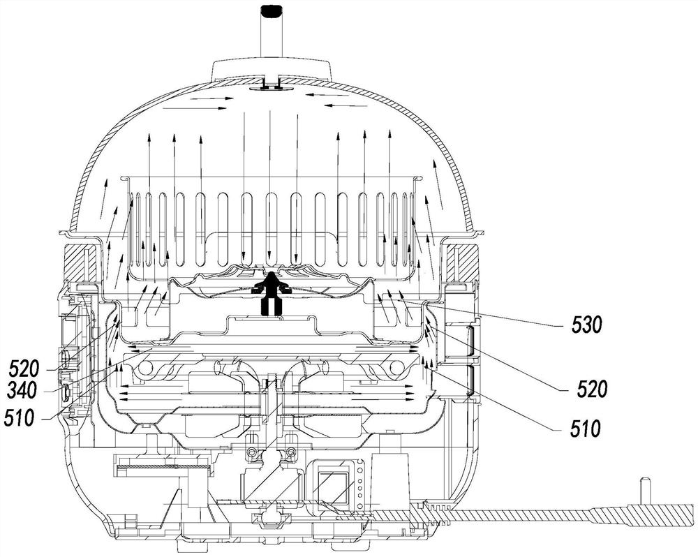
However, due to the existence of the hole, the hot air can enter the container and flow back from the container to the heating device. The hot air from various directions collides, turbulent flow is easy to occur, and the hot air circulation cannot be carried out normally.
[0006] In addition, the food itself or the grease produced by the food during cooking will block the hole of the container, resulting in that the hot air cannot return to the hot air fan through the hole to complete the hot air circulation after heating the food, and accumulate in the container, so the time spent on heating Longer, affecting the taste of food cooking

Method used


Image

  • A high-efficiency hot air cooking device
  • A high-efficiency hot air cooking device
  • A high-efficiency hot air cooking device

Examples


Embodiment Construction

[0050] The technical solutions of the embodiments of the present invention will be explained and described below in conjunction with the accompanying drawings of the embodiments of the present invention, but the following embodiments are only preferred embodiments of the present invention, not all of them. Based on the examples in the implementation manners, other examples obtained by those skilled in the art without making creative efforts all belong to the protection scope of the present invention.

[0051] In describing the present invention, it should be understood that the terms "center", "longitudinal", "transverse", "length", "width", "thickness", "upper", "lower", "front", " The orientations or positional relationships indicated by "rear", "left", "right", "vertical", "horizontal", "top", "bottom", "inner", "clockwise", "counterclockwise" are based on the attached The orientation or positional relationship shown in the figure is only for the convenience of describing t...


PUM


Abstract

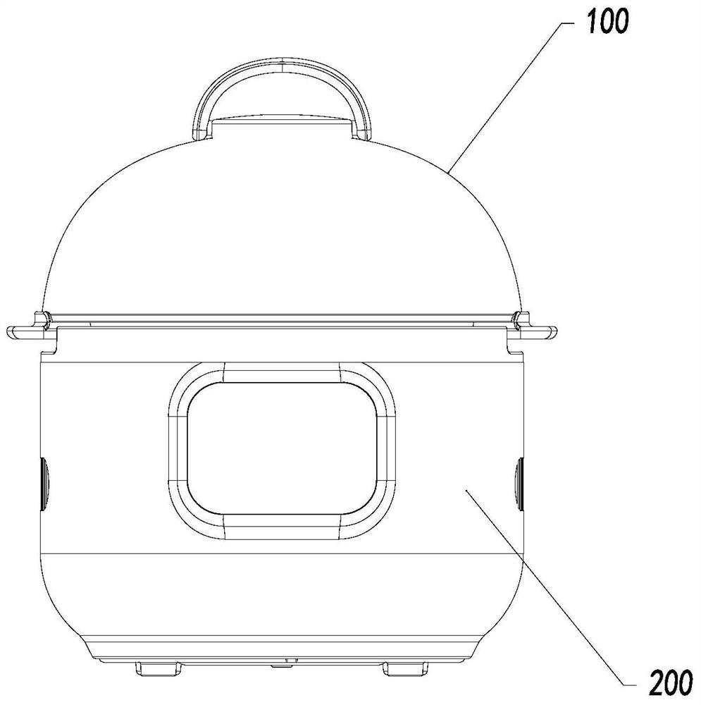
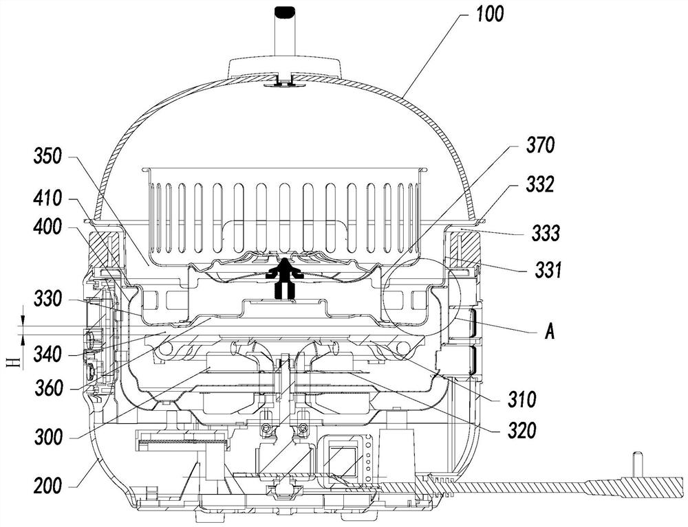
The invention discloses a high-efficiency hot air cooking device, which comprises a pot body and a pot cover that covers the pot body; a hot air assembly and a reflection cover for containing the hot air assembly are arranged inside the pot body; the hot air assembly It includes a heating device, a fan arranged below the heating device and a pressurized cover arranged above the heating device; a cooking space is formed inside the pressurized cover; there is a radiation between the pressurized cover and the heating device Gap; a first wind pressure air duct is formed between the heating device and the inner wall of the reflection cover, and a second wind pressure air duct is formed between the inner wall of the reflection cover and the pressurization cover; blown out by the fan The wind flows through the heating device and enters the plenum cover through the first wind pressure duct and the second wind pressure duct, and passes through the first wind pressure duct and the second wind pressure duct. The coordinated air flow at the air duct sucks the hot air in the radiation gap into the pressurized hood; to achieve high-efficiency hot air cooking.

Description

【Technical field】 [0001] The invention relates to the technical field of kitchen utensils, in particular to a high-efficiency hot air cooking device. 【Background technique】 [0002] Cooking utensils (such as air fryers) usually have two positions for setting the heating device. One is to set the heating device on the pot cover so that the cooking utensil can cook in different states by changing different pot covers. The other is to arrange the heating device at the bottom of the pot body to simplify the structure of the pot cover, reduce the weight of the pot cover, and facilitate the user to pick and place. [0003] For the cooking utensil with the heating device arranged at the bottom of the pot body, there are generally two heat flow modes in the cooking cavity. [0004] One way is that the heat is blown to the pot cover by the hot air fan of the heating device, and the hot air collides with the pot cover to change the flow direction, flow downward, enter the container c...

Claims


Application Information

Patent Timeline
Patent Type & Authority Patents(China)
IPC IPC(8): A47J37/06
CPCA47J37/0623A47J37/0641A47J37/0664
Inventor 朱泽春简威章君广韩阳
Owner JOYOUNG CO LTD
Learn More