Wind turbine, wind turbine rotor blade and blade bearing for a wind turbine

A technology of rotor blades and supporting devices, which is applied in wind power generation, mechanical equipment, and wind turbines in the same direction as the wind. It can solve problems such as bolt overload and achieve the effect of reducing the use of materials

Pending Publication Date: 2021-07-20
WOBBEN PROPERTIES GMBH
View PDF9 Cites 0 Cited by
  • Summary
  • Abstract
  • Description
  • Claims
  • Application Information

AI Technical Summary

Problems solved by technology

However, if the rotor blade diameter is selected to be very small for the corresponding blade length, for example for transport reasons or to save material, then the longitudinal forces and thus the local moments caused by the deflection are increased, so that the flange connection and especially the flange connection The bolts of the flange connection will be overloaded

Method used


Image

  • Wind turbine, wind turbine rotor blade and blade bearing for a wind turbine
  • Wind turbine, wind turbine rotor blade and blade bearing for a wind turbine
  • Wind turbine, wind turbine rotor blade and blade bearing for a wind turbine

Examples


Embodiment Construction

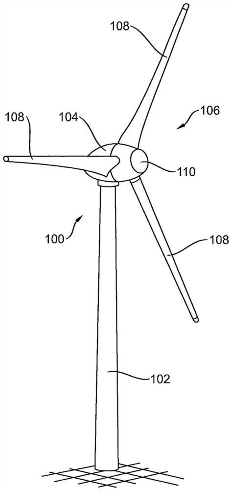
[0036] figure 1 A wind energy installation 100 is shown with a tower 102 and a nacelle 104 . A rotor 106 with three rotor blades 108 and a spinner 110 is arranged on the pod 104 . The rotor blade 108 is arranged with its rotor blade flange on the rotor hub. The rotor 106 is set in rotational motion by the wind in operation and thus drives a (not shown) generator in the nacelle 104 .

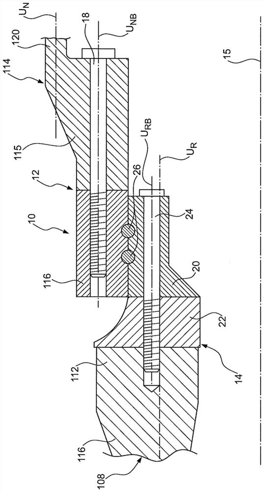
[0037] figure 2 show the basis figure 1 cutaway view of a part of a wind energy plant. The rotor blades 108 are here rotatably mounted on the rotor hub 114 by means of the blade bearing 10 .

[0038] The rotor blades 108 and the hub 114 are formed coaxially to the bearing 10 and symmetrically about the axis of rotation 15 .

[0039] The rotor blade 108 includes a rotor blade flange 112 and a blade lamination 116 extending in the longitudinal direction of the rotor blade 108 . The blade laminate 116 is preferably made of fiber composite material with a central circumference U R hollow col...


PUM


Abstract

The disclosure concerns a wind turbine, comprising: a hub with a hollow cylindrical region with a mean circumference UN; at least one rotor blade mounted rotatably on the hub, with a blade laminate which extends in the longitudinal direction of the rotor blade and at least in portions forms a hollow cylinder with a mean circumference UR; and at least one blade bearing for mounting the rotor blade on the hub, with a first bearing ring which is arranged on the hub side and connected by means of a first flange connection to a rotor hub flange formed on a rotor-blade side end portion of the hub, wherein the first flange connection has at least one hub longitudinal bolt which is arranged on a circumference UNB coaxially to the blade bearing; and a second bearing ring which is arranged on the rotor blade side and connected by means of a second flange connection to a rotor blade flange formed on a hub-side end portion of the rotor blade, wherein the second flange connection has at least one rotor blade longitudinal bolt which is arranged on a circumference URB coaxially to the blade bearing. The disclosure achieves the fundamental object in that a first radial offset V1 is formed between the circumference UN and the circumference UNB, and / or a second radial offset V2 is formed between the circumference URB and the circumference UR. In a further aspect, the disclosure achieves the fundamental object with a wind turbine rotor blade and a rotor blade bearing.

Description

technical field [0001] The invention relates to a wind energy installation comprising a hub with a hollow cylindrical area with a central circumference U N ; at least one rotor blade mounted rotatably on the hub with a blade laminate extending in the longitudinal direction of the rotor blade and at least partially formed with a central circumference U R and at least one blade support device for supporting the rotor blades on the hub, said blade support device having a first bearing ring arranged on the hub side, said first bearing ring being arranged by means of a first flange The connecting device is connected to the rotor hub flange, which is formed on the end section of the hub on the rotor blade side, wherein the first flange connecting device has at least one hub longitudinal screw, which is connected to the blade The supporting device is arranged coaxially on the circumference U NB and a second bearing ring arranged on the rotor blade side, which is connected to the ro...

Claims


Application Information

Patent Timeline
Patent Type & Authority Applications(China)
IPC IPC(8): F03D1/06F03D80/70
CPCF03D80/70F03D1/0658F05B2260/79Y02E10/72F03D1/0675F05B2240/30F05B2260/301
Inventor 拉斯马斯·伯尔歇斯法利科·比尔克纳约尔格·许勒尔
Owner WOBBEN PROPERTIES GMBH
Why Eureka
Try Eureka