Supercharge Your Innovation With Domain-Expert AI Agents!

cooling fan for laptop

A technology for notebook computers and cooling fans, which is applied to components of pumping devices for elastic fluids, non-variable-capacity pumps, pump components, etc., can solve the problems of loud fan noise and affecting the comfort of users of electronic products, etc. Achieve the effect of improving heat dissipation performance, improving reliability and service life, and improving bonding strength

Active Publication Date: 2022-02-08
昆山品岱电子有限公司
View PDF9 Cites 0 Cited by
  • Summary
  • Abstract
  • Description
  • Claims
  • Application Information

AI Technical Summary

Problems solved by technology

However, the noise of the fans used in existing electronic products is relatively large, which affects the comfort of users of electronic products

Method used


Image

  • cooling fan for laptop
  • cooling fan for laptop
  • cooling fan for laptop

Examples


Embodiment 1

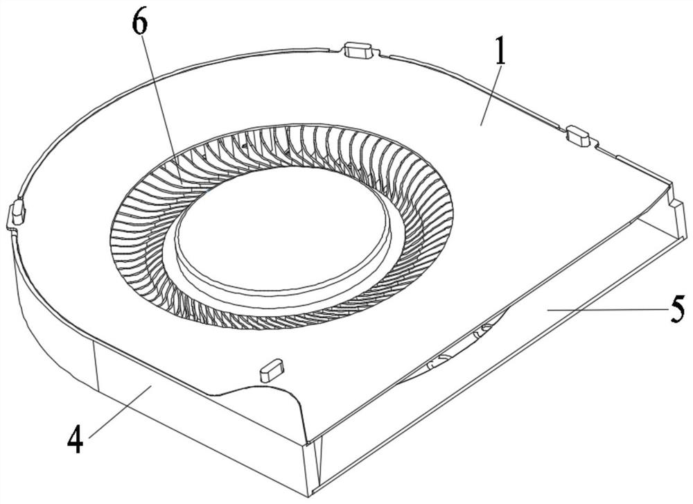
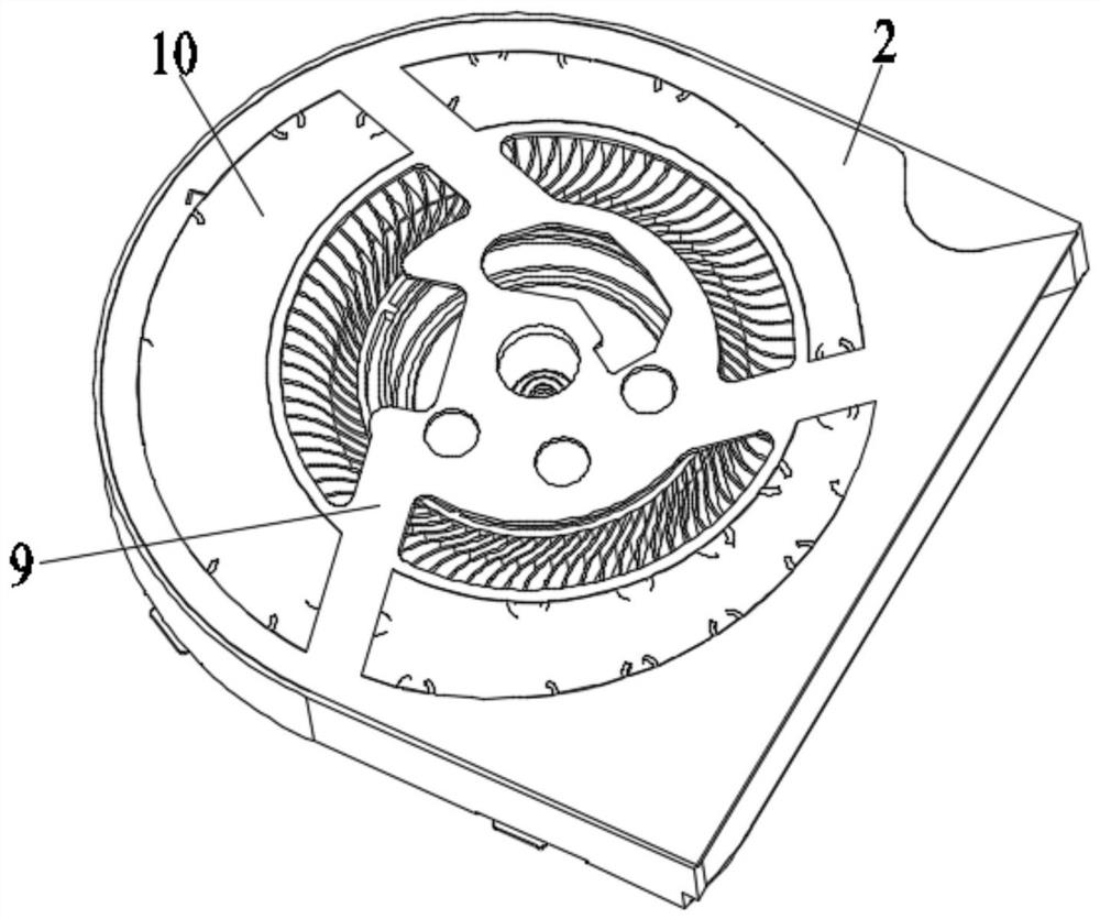
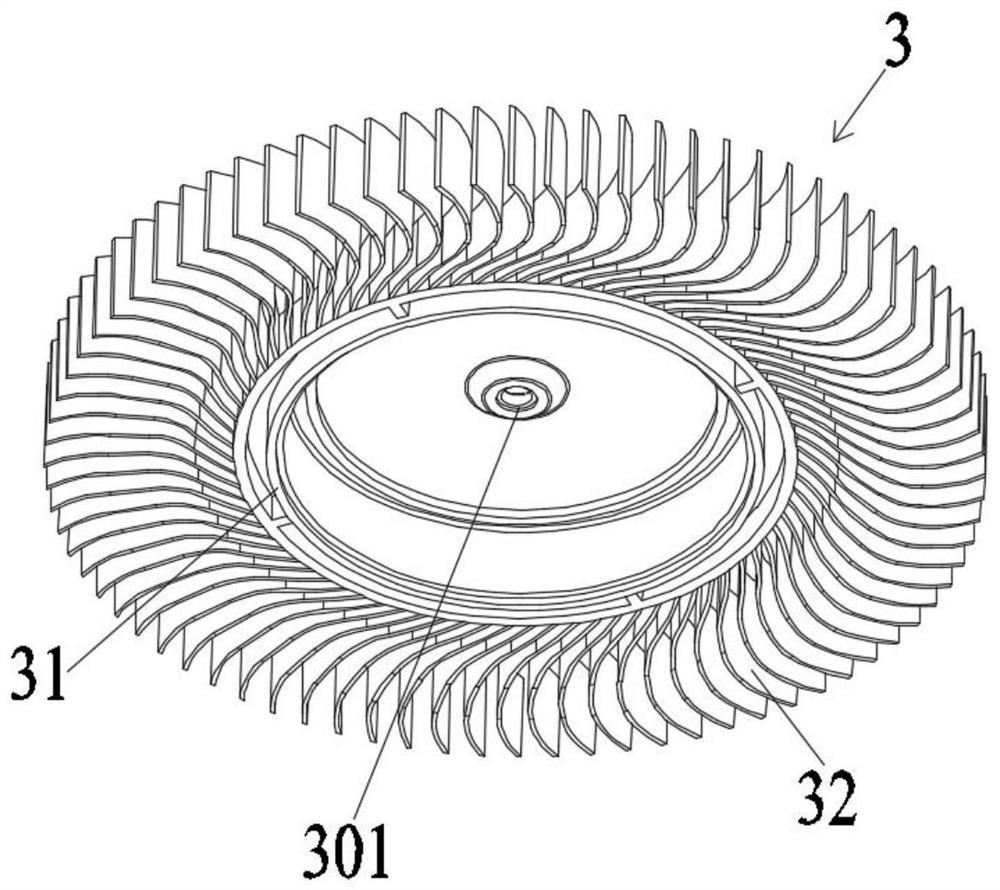
[0022] Embodiment 1: A cooling fan for a notebook computer, comprising: an upper cover 1, a metal base 2, and an impeller 3 located between the upper cover 1 and the metal base 2, and the edge of the metal base 2 has a side wall Plate 4, an air outlet 5 is opened on one side of the side wall plate 4, an upper air inlet 6 is opened on the upper cover plate 1, a positioning cylinder 7 is arranged at the center of the metal bottom plate 2, and the impeller 3 further includes a bottom There is a hub 31 with a shaft core rotor part 301 and several blades 32 arranged at intervals on the outer wall of the hub 31. The shaft core rotor part 301 of the impeller 3 is connected with the positioning cylinder 7 of the metal base plate 2 in rotation; The blade 32 of the impeller 3 is arc-shaped in the radial direction, and the height of the blade 32 of the impeller 3 gradually increases from the side close to the hub 31 to the side away from the hub 31;

[0023] The inner wall of the strip-s...

Embodiment 2

[0028] Embodiment 2: A cooling fan for a notebook computer, comprising: an upper cover 1, a metal base 2, and an impeller 3 located between the upper cover 1 and the metal base 2, and the edge of the metal base 2 has a side wall Plate 4, an air outlet 5 is opened on one side of the side wall plate 4, an upper air inlet 6 is opened on the upper cover plate 1, a positioning cylinder 7 is arranged at the center of the metal bottom plate 2, and the impeller 3 further includes a bottom There is a hub 31 with a shaft core rotor part 301 and several blades 32 arranged at intervals on the outer wall of the hub 31. The shaft core rotor part 301 of the impeller 3 is connected with the positioning cylinder 7 of the metal base plate 2 in rotation; The blade 32 of the impeller 3 is arc-shaped in the radial direction, and the height of the blade 32 of the impeller 3 gradually increases from the side close to the hub 31 to the side away from the hub 31;

[0029] The inner wall of the strip-s...


PUM


Abstract

The invention discloses a cooling fan for a notebook computer, comprising: an upper cover plate, a metal base plate and an impeller located between the upper cover plate and the metal base plate, the blades of the impeller are arc-shaped in the radial direction, and the The height of the blades of the impeller increases gradually from the side close to the hub to the side away from the hub; the inner wall of the strip-shaped through hole of the metal base plate is provided with several pairs of arc-shaped branches at intervals, and two arc-shaped branches in each pair of arc-shaped branches The support bars are arranged facing each other, and the arc-shaped support bars are embedded in the side wall of the plastic sheet layer; the metal bottom plate is located on the periphery of the positioning cylinder and has several strip-shaped through holes at intervals along the circumferential direction, adjacent to the strip-shaped through-holes There is a reinforcing rib between them, and the surface of the plastic plate layer facing the impeller is provided with several outwardly protruding protrusions at intervals. The heat dissipation fan of the present invention not only reduces the overall weight of the axial fan, but also reduces the noise generated when the gas enters the impeller from the air inlet along the axial direction and then is discharged from the impeller along the radial direction under the pressure difference, thereby bringing comfort to the user .

Description

technical field [0001] The invention relates to a heat dissipation fan for a notebook computer, belonging to the field of heat dissipation of electronic products. Background technique [0002] As people pay more and more attention to the quality of life and taste, the pursuit of technology is becoming more and more perfect. Portable and trendy electronic devices such as notebook computers are also tending to be thinner and more refined. The cooling fan is a very important cooling module for computer products (especially notebook computers), because the temperature will directly affect the operating performance, stability and service life of the CPU, and the structural design of the cooling fan is also relatively with the computer The design development trend of product form changes. However, the noise of the fan used in the existing electronic products is relatively high, which affects the comfort of users of the electronic products. Contents of the invention [0003] Th...

Claims


Application Information

Patent Timeline
Patent Type & Authority Patents(China)
IPC IPC(8): F04D25/08F04D29/30F04D29/42F04D29/66
CPCF04D25/08F04D29/30F04D29/4226F04D29/666F04D29/282F04D29/663G06F1/203Y02D10/00
Inventor 何克锋李龙
Owner 昆山品岱电子有限公司
Features
  • R&D
  • Intellectual Property
  • Life Sciences
  • Materials
  • Tech Scout
  • Unparalleled Data Quality
  • Higher Quality Content
  • 60% Fewer Hallucinations
Learn More