Vibration type safe snow removal solar street lamp

A solar street light and vibrating technology, which is applied in energy-saving lighting, circuit layout, outdoor lighting, etc., can solve the problem that photovoltaic panels are easily covered by snow, and achieve the effect of ensuring sufficient light reception, avoiding safety accidents, and good snow removal effect

Pending Publication Date: 2021-07-20
蔡永爱
View PDF0 Cites 5 Cited by
  • Summary
  • Abstract
  • Description
  • Claims
  • Application Information

AI Technical Summary

Problems solved by technology

[0005] The purpose of the present invention is to solve the problem that the above-mentioned photovoltaic panels are easily covered by snow, and provide a vibration-type safe snow-removing solar street light that can remove snow on the surface of photovoltaic panels.

Method used


Image

  • Vibration type safe snow removal solar street lamp
  • Vibration type safe snow removal solar street lamp

Examples


Embodiment 1

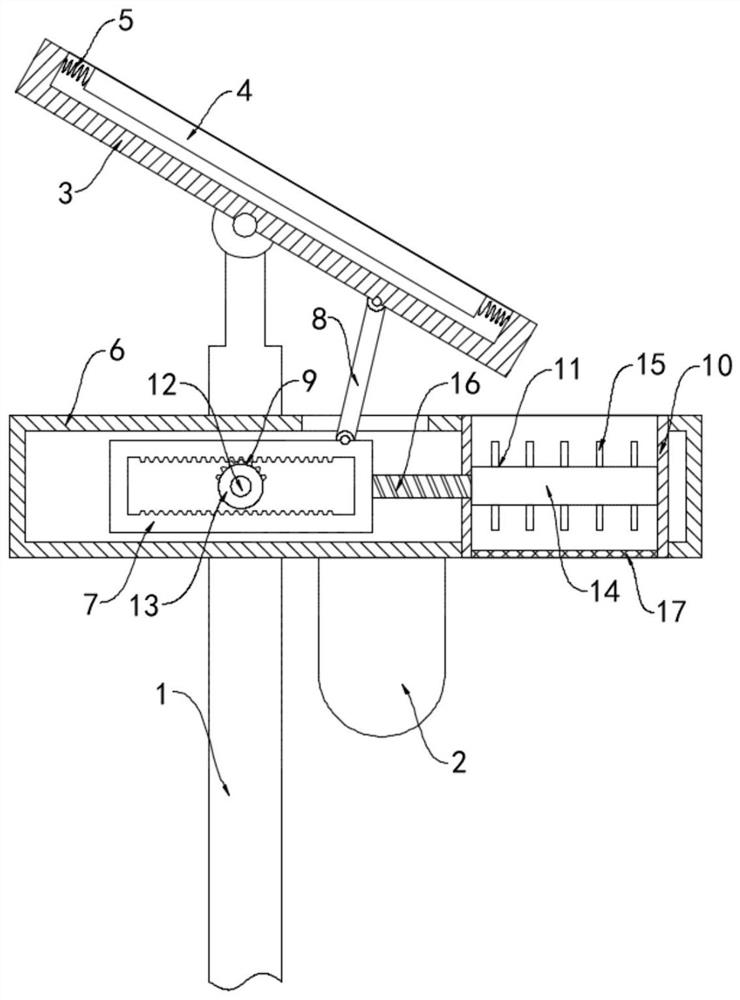
[0022] like figure 1 As shown, a vibrating solar street lamp for safe snow removal includes a light pole 1 and a lighting lamp 2. The top of the light pole 1 is rotatably connected with a mounting groove 3, and the top of the light pole 1 is hinged to the bottom of the mounting groove 3 through a hinge. 3 is installed with a photovoltaic panel 4, and the two ends of the photovoltaic panel 4 are fixedly connected to the inner wall of the installation groove 3 through springs 5 ​​respectively.

[0023] In this embodiment, a control box 6 is fixedly connected to the light pole 1, and the lighting lamp 2 is fixedly installed on the bottom of the control box 6. A sliding frame 7 is slidably connected to the control box 6, and a transmission rod 8 is rotatably connected to the sliding frame 7. The upper end of the transmission rod 8 extends to the outside of the control box 6 and is rotatably connected with the bottom surface of the installation groove 3. The control box 6 is provid...

Embodiment 2

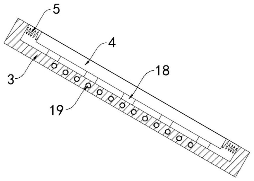
[0029] like figure 2 As shown, the difference between this embodiment and Embodiment 1 is that: the bottom surface of the photovoltaic panel 4 is equidistantly arranged with a plurality of permanent magnet blocks 18, and a plurality of closed coils 19 are embedded in the installation groove 3, and the closed coils 19 have a shape of Helically wound, when the permanent magnet block 18 slides reciprocally in the installation groove following the photovoltaic panel 14 , the closed coil 19 can cut the magnetic induction line of the permanent magnet block 18 to generate an induced current.

[0030] In this embodiment, when the photovoltaic panel 4 periodically reciprocates in the installation groove 3, it drives the permanent magnet block 18 to reciprocate and slide, and the closed coil 19 continuously cuts the magnetic field lines of the permanent magnet block 18 to generate an induced current, and the electric energy is converted into heat energy. The installation groove 3 is he...


PUM


Abstract

The invention belongs to the technical field of new energy street lamps, and particularly relates to a vibration type safe snow removal solar street lamp which comprises a lamp pole and a lighting lamp, the top end of the lamp pole is rotationally connected with a mounting groove, a photovoltaic panel is mounted in the mounting groove, and the two ends of the photovoltaic panel are fixedly connected with the inner wall of the mounting groove through springs correspondingly, a control box is fixedly connected to the lamp pole, the illuminating lamp is fixedly installed at the bottom of the control box, a sliding frame is slidably connected to the interior of the control box, a transmission rod is rotatably connected to the sliding frame, and the upper end of the transmission rod extends out of the control box and is rotatably connected with the bottom face of the installation groove, and a driving mechanism for driving the sliding frame to move is arranged in the control box. Snow on the surface of the photovoltaic panel can be shaken off through reciprocating deflection and vibration of the photovoltaic panel, the situation that the power generation efficiency is affected due to the fact that light is shielded by the snow is prevented, the shaken-off snow is beaten and broken through the breaking mechanism, pedestrians are prevented from being injured when the snow falls off, and the safety performance of the device is improved.

Description

technical field [0001] The invention belongs to the technical field of new energy street lamps, in particular to a vibrating solar street lamp for safe snow removal. Background technique [0002] Street lamps are an important tool for road lighting. Most of them are installed in the open-air environment on both sides of the road. With the development and application of new energy technology, solar street lamps have emerged as the times require, which greatly reduces the cost of electricity for urban road lighting and reflects energy conservation and emission reduction. environmental protection concept. [0003] When traditional new energy street lamps are in heavy snow, the photovoltaic panels are easily covered by snow, which blocks the light and cannot supply power to the street lights. In severe cases, the photovoltaic panels may even be damaged due to heavy snow, causing major economic losses. Some snow removal devices can only push the snow off the photovoltaic panels,...

Claims


Application Information

Patent Timeline
Patent Type & Authority Applications(China)
IPC IPC(8): F21S9/03F21V23/00F21V33/00H02S40/12H02S20/30F21W131/103
CPCF21S9/035F21V23/003F21V33/00F21W2131/103H02S20/30H02S40/12Y02B20/72Y02E10/50
Inventor 蔡永爱
Owner 蔡永爱
Why Eureka
Try Eureka