
Thermal control structure and storage battery structure comprising same

A battery pack and thermal control technology, which is applied to secondary batteries, circuits, electrical components, etc., can solve problems such as heat dissipation, difficulty in thermal control design, pressure, etc., and achieve the effect of preventing severe fluctuations in temperature

Active Publication Date: 2021-07-20
航天科工空间工程发展有限公司
View PDF6 Cites 0 Cited by
  • Summary
  • Abstract
  • Description
  • Claims
  • Application Information

AI Technical Summary

Problems solved by technology

[0003] As the power consumption of the satellite becomes higher and higher, the load of the satellite increases, which leads to an increase in the heat consumption of the battery, and then the whole satellite needs to provide a larger heat dissipation surface for the battery, and heat the battery when the heat consumption of the battery is high. Dissipation; when the heat dissipation of the battery is low under low temperature conditions, the whole star will provide electric heating for the battery to compensate the thermal power consumption, so as to ensure that the temperature of the battery is not lower than the lower limit of the working temperature. The compensation power consumption of the star-to-battery is also increasing, which puts a great pressure on the energy of the whole star
At the same time, the heat consumption of the battery will also change with the charging state, temperature, charging rate, and discharge load. Therefore, it is extremely difficult to guarantee the temperature requirements and temperature difference requirements of the battery, and the difficulty of thermal control design is also increasing.

Method used


Image

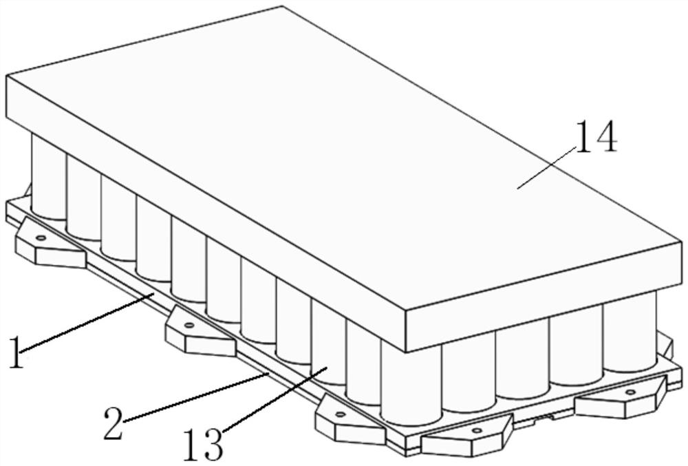
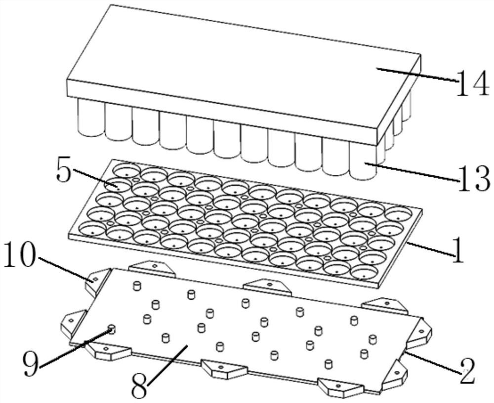
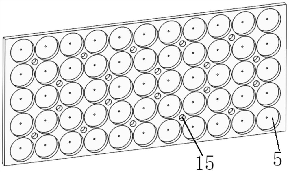
  • Thermal control structure and storage battery structure comprising same
  • Thermal control structure and storage battery structure comprising same
  • Thermal control structure and storage battery structure comprising same

Examples


Embodiment Construction

[0035] Various exemplary embodiments of the present invention will now be described in detail with reference to the accompanying drawings. It should be noted that the relative arrangements of components and steps, numerical expressions and numerical values ​​set forth in these embodiments do not limit the scope of the present invention unless specifically stated otherwise.

[0036] The following description of at least one exemplary embodiment is merely illustrative in nature and in no way taken as limiting the invention, its application or uses.

[0037] Techniques and devices known to those of ordinary skill in the relevant art may not be discussed in detail, but where appropriate, such techniques and devices should be considered part of the description.

[0038] In all examples shown and discussed herein, any specific values ​​should be construed as exemplary only, and not as limitations. Therefore, other instances of the exemplary embodiment may have different values.

...


PUM


Abstract

The invention provides a thermal control structure and a storage battery structure comprising the thermal control structure. The thermal control structure comprises a uniform-temperature phase-change composite board, the variable heat-conducting three-dimensional plate is positioned below the uniform-temperature phase-change composite plate; the uniform-temperature phase-change composite plate comprises a uniform-temperature cavity and a phase-change cavity, the phase-change cavity is located above the uniform-temperature cavity, a working medium is contained in the uniform-temperature cavity, and a phase-change material is contained in the phase-change cavity; the uniform-temperature phase-change composite plate comprises a mounting groove positioned above the uniform-temperature cavity; the variable thermal conductivity three-dimensional plate comprises a thermal conductivity cavity and a non-condensable gas storage cavity communicated with the thermal conductivity cavity, the height of the non-condensable gas storage cavity on the horizontal plane is larger than that of the thermal conductivity cavity, a working medium is contained in the thermal conductivity cavity, non-condensable gas is contained in the non-condensable gas storage cavity, and the non-condensable gas is helium. The temperature difference between the single batteries in the storage battery pack is effectively reduced, it is guaranteed that all the single batteries have the same charging and discharging rate, and the thermal resistance with the outside world is changed according to the heat dissipation requirement of the storage battery pack.

Description

technical field [0001] The invention relates to the technical field of thermal control. More specifically, it relates to a thermal control structure and a battery structure including the thermal control structure. Background technique [0002] The temperature of the battery is an important factor to ensure its life. Generally, the temperature of the lithium-ion battery is required to be 10 to 30°C. And in order to ensure that all battery cells have the same charge and discharge rate, the temperature difference between all battery packs and the battery cells in the battery pack is required to be less than 5°C, and even more stringently required to be less than 3°C. [0003] As the power consumption of the satellite becomes higher and higher, the load of the satellite increases, which leads to an increase in the heat consumption of the battery, and then the whole satellite needs to provide a larger heat dissipation surface for the battery, and heat the battery when the heat c...

Claims


Application Information

Patent Timeline
Patent Type & Authority Applications(China)
IPC IPC(8): H01M10/617H01M10/635H01M10/6554H01M10/659H01M10/658
CPCH01M10/617H01M10/635H01M10/6554H01M10/659H01M10/658Y02E60/10
Inventor 李子轩赵益涛刘嫣洁隋愿愿段友东于印
Owner 航天科工空间工程发展有限公司
Learn More