
Cutting fluid circulating treatment equipment and method for determining treatment efficiency of cutting fluid circulating treatment equipment

A circulating treatment and cutting fluid technology, applied in separation methods, chemical instruments and methods, sanitary equipment for toilets, etc., can solve the problems of high waste liquid treatment costs, achieve volume reduction, improve sterilization efficiency, and complete sterilization and disinfection Effect

Pending Publication Date: 2021-07-23
BEIJING AEROSPACE SANFA HIGH TECH
View PDF0 Cites 0 Cited by
  • Summary
  • Abstract
  • Description
  • Claims
  • Application Information

AI Technical Summary

Problems solved by technology

[0006] At present, there are strict regulations in foreign countries restricting the use of certain cutting fluids, and the cost of waste liquid treatment is extremely high. For example, waste liquid treatment in Germany costs about 1 billion euros per year.

Method used


Image

  • Cutting fluid circulating treatment equipment and method for determining treatment efficiency of cutting fluid circulating treatment equipment
  • Cutting fluid circulating treatment equipment and method for determining treatment efficiency of cutting fluid circulating treatment equipment
  • Cutting fluid circulating treatment equipment and method for determining treatment efficiency of cutting fluid circulating treatment equipment

Examples


Embodiment Construction

[0056]In describing the present invention, it should be understood that the terms "center", "longitudinal", "transverse", "length", "width", "thickness", "upper", "lower", "front", " Back", "Left", "Right", "Vertical", "Horizontal", "Top", "Bottom", "Inner", "Outer", "Clockwise", "Counterclockwise", "Axial", The orientation or positional relationship indicated by "radial", "circumferential", etc. is based on the orientation or positional relationship shown in the drawings, and is only for the convenience of describing the present invention and simplifying the description, rather than indicating or implying the referred device or element Must be in a particular orientation, be constructed in a particular orientation, and operate in a particular orientation, and therefore should not be construed as limiting the invention. In addition, the features defined as "first" and "second" may explicitly or implicitly include one or more of these features. In the description of the presen...


PUM


Abstract

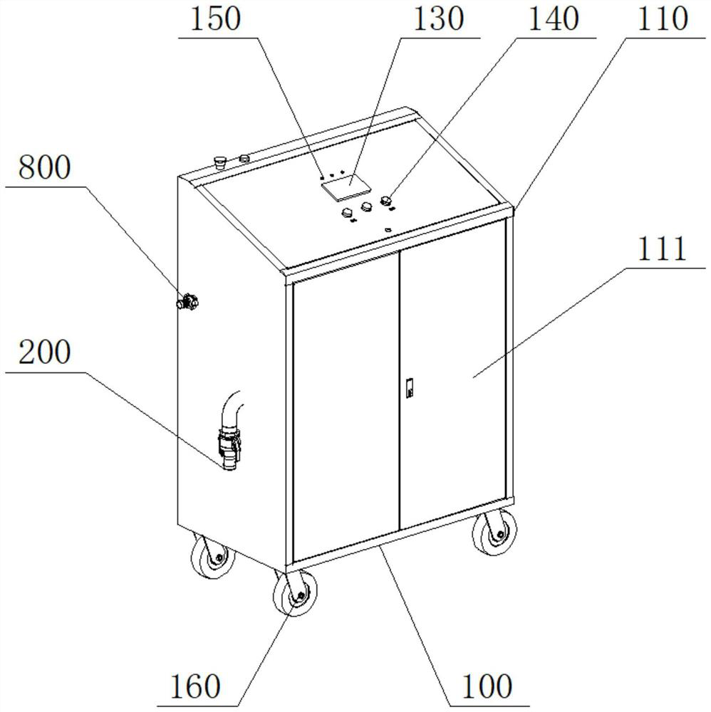
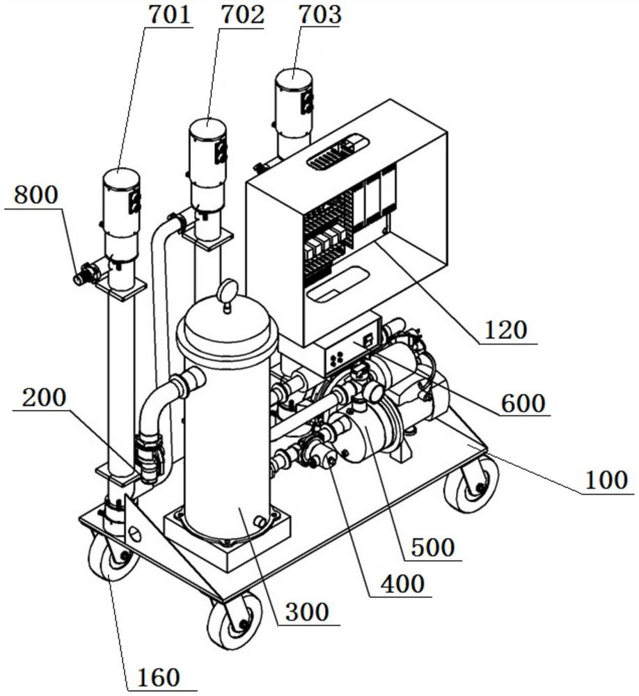
Cutting fluid circulation treatment equipment comprises a base; an equipment liquid inlet, a filtering device, an electromagnetic valve, a self-sucking pump, a descaling device, a disinfection device and an equipment liquid outlet, which are sequentially communicated through pipes; the disinfection device comprises a first disinfection device, a second disinfection device and a third disinfection device which are sequentially connected in series; a disinfection pipe liquid inlet of the third disinfection device is communicated with a liquid outlet of the descaling device through a pipeline, and a disinfection pipe liquid outlet of the first disinfection device is communicated with an equipment liquid outlet through a pipeline. The cutting fluid circulating treatment equipment is provided with three same ultraviolet disinfection pipes which are connected in series for use, so that the sterilization and disinfection efficiency of the equipment is improved.

Description

technical field [0001] The invention belongs to the technical field of cutting fluid treatment in the field of energy saving and environmental protection of mechanical processing in the environmental protection industry, and in particular relates to a cutting fluid circulation treatment equipment and a method for determining its treatment efficiency. Background technique [0002] At present, the pollution caused by cutting processing methods at home and abroad is still very large. Non-traditional dry machining methods such as dry cutting, jet cooling and liquid nitrogen cooling have appeared, but dry machining methods also have their shortcomings that are difficult to solve. Therefore, it is still relatively far away from wet machining that completely replaces water-based cutting fluids. High-performance green The development of environment-friendly water-based metal cutting fluid is still of great significance. Metal cutting fluid is widely used in machining process to pla...

Claims


Application Information

Patent Timeline
Patent Type & Authority Applications(China)
IPC IPC(8): B01D36/00A61L2/10A61L2/26A61L2/24C10M175/00
CPCB01D36/00A61L2/10A61L2/26A61L2/24C10M175/00
Inventor 王慕雪张帆李旭东周培好王伟丽
Owner BEIJING AEROSPACE SANFA HIGH TECH
Learn More