
Downward-moving type tight die capable of implementing overall rapid movement-out of part

A fast and integrated technology, applied in the field of molds, can solve the problems of damage to molded products, poor versatility, affecting the qualified rate of product injection, and achieve the effect of avoiding damage and improving versatility

Inactive Publication Date: 2021-07-23
谭健华
View PDF1 Cites 0 Cited by
  • Summary
  • Abstract
  • Description
  • Claims
  • Application Information

AI Technical Summary

Problems solved by technology

[0006] The purpose of the present invention is to provide a down-moving compact mold that can realize the rapid removal of parts as a whole, so as to solve the existing injection mold structure on the market proposed by the above-mentioned background technology. When producing products, the entire upper mold needs to be removed to take out the molded product, and the lower half of the molded product is still inside the cavity of the lower mold. When taking it out, it is necessary to clamp the upper part of the mold body. This way of taking out , it is easy to cause damage to the molded product and affect the qualified rate of product injection molding, and the mold cavity inside the upper mold and the lower mold is a fixed shape. When a mold is used to mold parts with a fixed shape, when it is necessary to inject parts of other shapes, it needs Replacing the entire mold, the problem of poor versatility

Method used


Image

  • Downward-moving type tight die capable of implementing overall rapid movement-out of part
  • Downward-moving type tight die capable of implementing overall rapid movement-out of part
  • Downward-moving type tight die capable of implementing overall rapid movement-out of part

Examples


Embodiment Construction

[0026] Based on the embodiments of the present invention, all other embodiments obtained by persons of ordinary skill in the art without making creative efforts belong to the protection scope of the present invention.

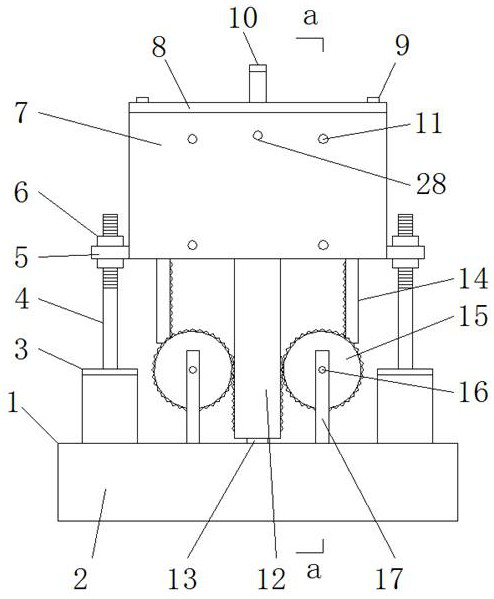
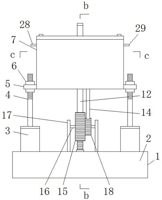
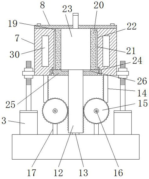
[0027] see Figure 1-7, the present invention provides a technical solution: a down-moving compact mold that can realize the rapid removal of parts as a whole, including a mold mounting frame 1, a base 2, a telescopic mechanism 3, a support rod 4, a connecting plate 5, an adjusting nut 6, an outer Die body 7, sealing top plate 8, fastening bolt 9, pouring pipe 10, limit bolt 11, lifting rod 12, touch switch 13, lower pressing rod 14, external gear plate 15, rotating shaft 16, support frame 17, Inner gear plate 18, installation chamber 19, inner mold body 20, limit slide bar 21, limit groove 22, inner mold cavity 23, installation groove 24, sealing bottom plate 25, storage groove 26, support template 27, water inlet pipe 28, Outlet pipe 29 and cooling chamber 3...


PUM


Abstract

The invention discloses a downward-moving type tight die capable of implementing overall rapid movement-out of a part, which comprises a die mounting frame, a base, a telescopic mechanism, a support rod, a connecting plate, an adjusting nut, a fastening bolt, a pouring pipe, a limiting bolt, a point contact switch, an outer gear disc, a rotating shaft, a support frame, an inner gear disc, a water inlet pipe, a water outlet pipe and a cooling cavity. The water inlet pipe and the water outlet pipe are respectively arranged on the front side and the rear side of an outer die body; and the inner ends of the water inlet pipe and the water outlet pipe communicate with the cooling cavity inside the side wall of the outer die body. According to the downward-moving type tight die capable of implementing overall rapid movement-out of the part, by improving an existing die structure, overall pushing-out of a formed product in a die cavity is implemented, and the part in the die cavity does not need to be taken through a tool or a hand so as to effectively avoid the possibility that the formed part is damaged; and a mounting bin is arranged inside the outer die body, and an inner die body with different inner die cavities can be replaced according to the processing requirements, so that the universality of injection molding processing of the die is improved.

Description

technical field [0001] The invention relates to the technical field of moulds, in particular to a down-moving compact mould, which can realize rapid removal of parts as a whole. Background technique [0002] Molds are mainly products of specific shapes obtained through injection molding, blow molding, die-casting or forging molding in industrial production. Molds are tools used to make shaped objects. For example, reference documents: Application number: CN201210047201.8, date of authorization announcement: 20140702 A circuit device for cooling water entering and exiting one side of an injection mold, including a water baffle, a water plug, a support plate, a plug, a water inlet, a return channel, an outlet, and a turning water cooling hole. In the present invention, the water turning cooling hole composed of several straight blind holes is arranged in the mould, and the water turning cooling hole is divided into two upper and lower water turning chambers and a return chambe...

Claims


Application Information

Patent Timeline
Patent Type & Authority Applications(China)
IPC IPC(8): B29C45/40B29C45/64B29C45/26
CPCB29C45/2675B29C45/4005B29C45/64B29C2045/4042
Inventor 谭健华
Owner 谭健华
Learn More