A cab floor assembly and truck

A cab and floor technology is applied in the field of collision safety performance design of trucks. Bending resistance and fatigue resistance, and the effect of improving fatigue resistance

Active Publication Date: 2022-04-19
ZHEJIANG GEELY HLDG GRP CO LTD +3
View PDF11 Cites 0 Cited by
  • Summary
  • Abstract
  • Description
  • Claims
  • Application Information

AI Technical Summary

Problems solved by technology

[0006] One purpose of this application is to solve the technical problem that the cab structure in the prior art cannot or does not significantly improve the living space of the abdomen and legs of the occupant in the longitudinal direction (ie, the X direction of the vehicle) after the collision

Method used


Image

  • A cab floor assembly and truck
  • A cab floor assembly and truck
  • A cab floor assembly and truck

Examples


Embodiment Construction

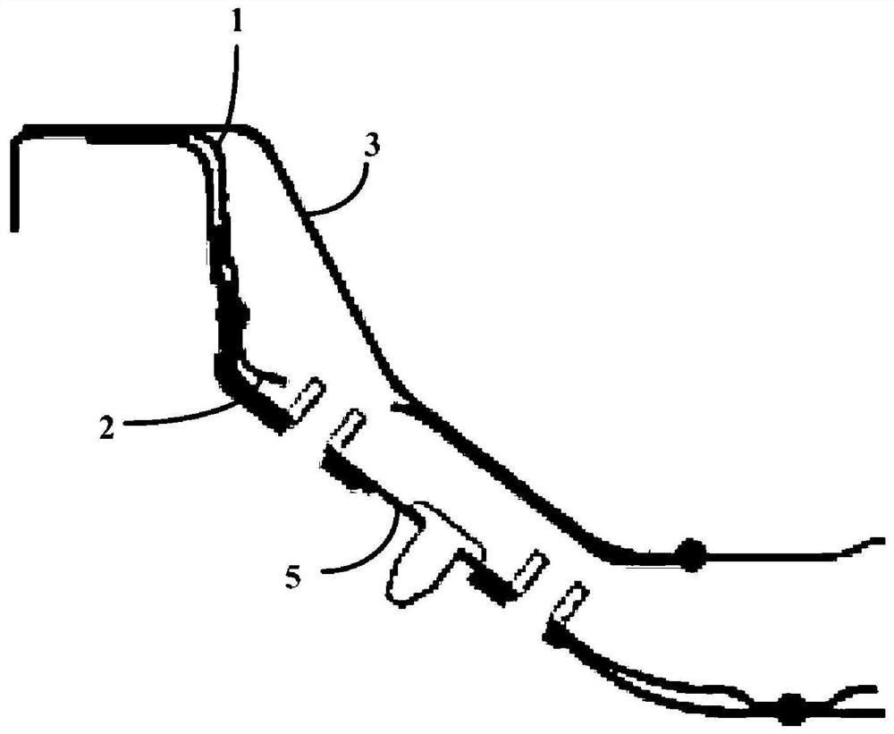
[0052] In the prior art, usually in order to increase the collision safety and structural strength of the cab floor assembly of trucks, reinforcements are usually stacked on related components, for example, at least one reinforcement is added at a position close to the front cross member of the floor, when When adding multiple reinforcements, multiple reinforcements are also stacked together, such as figure 1 As shown, in the prior art, the front beam reinforcement plate 2 is closely attached to the front beam 1 of the floor, and no cavity structure is formed between the two, that is to say, the front beam reinforcement plate 2 is stacked in front of the floor. on beam 1. However, this not only increases the cost but also does not conform to the idea of ​​lightweight design.

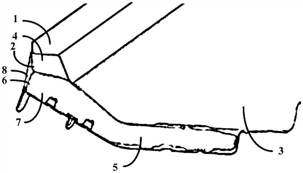
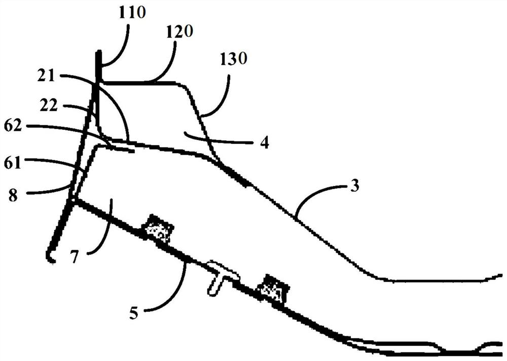
[0053] figure 2 A schematic perspective view of a partial structure of a cab floor assembly according to an embodiment of the present invention is shown. image 3 A schematic cross-sectional view of ...


PUM


Abstract

The invention provides a cab floor assembly and a truck. The cab floor assembly includes a front floor; a front cross member of the floor, which is connected to the front end of the front floor and extends along the transverse direction of the vehicle; The rear end of the floor front cross beam is connected to the front floor, the front cross beam reinforcement plate extends in the transverse direction, and a first cavity is formed between the front cross beam reinforcement plate and the floor front cross beam. According to the solution of the present invention, by redesigning the structure of the front beam reinforcement plate, a first cavity is formed between the front beam reinforcement plate and the floor front beam, thereby improving the bending resistance and collision energy absorption effect of the cab floor assembly, and further Avoid large collapse of the cab floor assembly in the longitudinal direction after a frontal collision of the vehicle, and ensure that the distance between the driver's knee and the instrument panel / steering column in the longitudinal direction will not change greatly, Avoid squeezing the driver's legs and abdomen.

Description

technical field [0001] The invention relates to the technical field of collision safety performance design of trucks, in particular to a cab floor assembly and a truck, and the truck may be an N2 flat-top truck. Background technique [0002] With the development of technology, the current regulations around the world have higher and higher requirements for occupant protection in truck cabs. The tonnage of heavy trucks is larger, and the cab space is larger. The cab can provide sufficient occupant protection, but light trucks are due to The tonnage is small, the cab space and structure are limited, and the cab generally fails to provide sufficient occupant protection like heavy trucks. The updated GB26512-2020 regulations have further improved the occupant protection requirements for cabs of vehicles weighing more than 7.5 tons, which is difficult for most existing light truck cabs in the domestic market. [0003] The cab floor of the light truck is mainly composed of front ...

Claims


Application Information

Patent Timeline
Patent Type & Authority Patents(China)
IPC IPC(8): B62D25/20
CPCB62D25/20
Inventor 刘朝冉金风云柴国民郑震李寅李红艳
Owner ZHEJIANG GEELY HLDG GRP CO LTD
Why Eureka
Try Eureka