Ship berthing chain stopper

A technology for chain stoppers and ships, which is applied in the direction of ships, etc. It can solve the problems of staff injury, fire, rust and impurities, etc., and achieve the effect of protecting windlass, preventing excessive speed, and preventing overload work

Inactive Publication Date: 2021-07-23
宋雪莲
View PDF0 Cites 2 Cited by
  • Summary
  • Abstract
  • Description
  • Claims
  • Application Information

AI Technical Summary

Problems solved by technology

[0003] However, the existing chain stoppers still have the following defects in actual use: when the ship needs to berth and anchor, the crew needs to continuously rotate the rod on the chain stopper to control the anchor chain on the anchor chain wheel in turn. If the sliding speed of the anchor chain is too high, the rust impurities on the anchor chain will fly around with the wind, which will be easily inhaled by the staff and cause injury to the staff. The anchor chain may cause sparks on the anchor chain machine due to the high speed, burn the anchor chain machine, and cause a fire. Therefore, when the anchor breaks down, the seaman needs to stop and release the anchor chain continuously, and constantly control the control lever. This is not only complicated and troublesome to operate, but also due to the high quality of the anchor chain itself, repeated stopping and loosening of the anchor chain is also a great test for the physical fitness of the staff

Method used


Image

  • Ship berthing chain stopper
  • Ship berthing chain stopper
  • Ship berthing chain stopper

Examples


Embodiment Construction

[0020] The following will clearly and completely describe the technical solutions in the embodiments of the present invention with reference to the accompanying drawings in the embodiments of the present invention. Obviously, the described embodiments are only some, not all, embodiments of the present invention. Based on the embodiments of the present invention, all other embodiments obtained by persons of ordinary skill in the art without making creative efforts belong to the protection scope of the present invention.

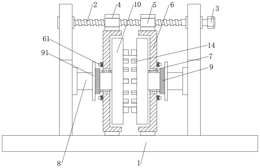
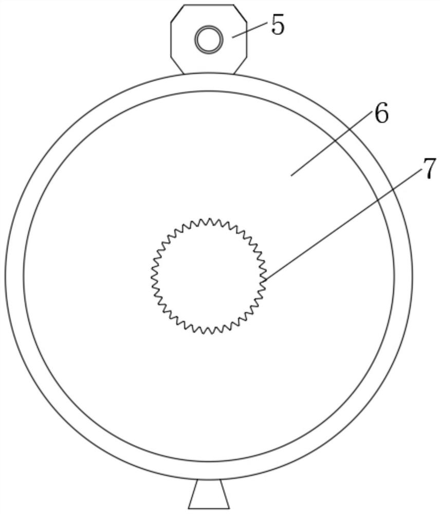
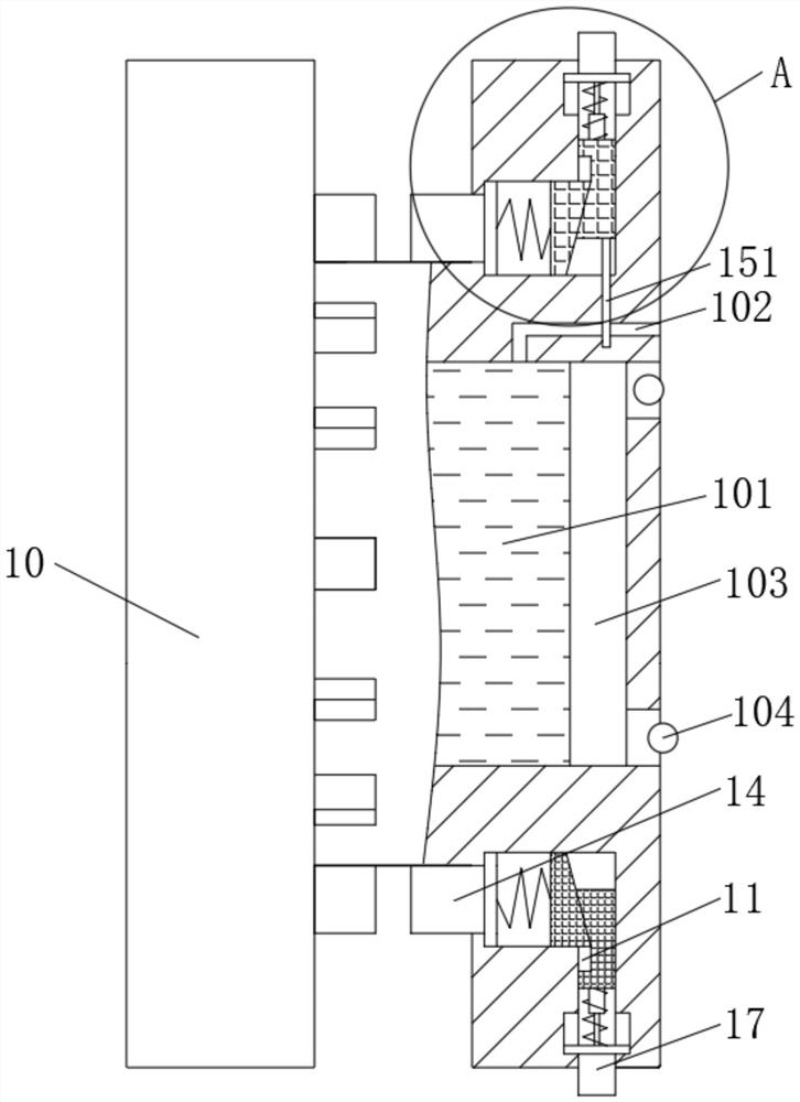
[0021] see Figure 1-5 , a chain stopper for berthing ships, comprising a base 1, the upper end of the base 1 is movably connected with a threaded rod 2, one end of the threaded rod 2 is fixedly connected with an adjusting nut 3, and the two sides of the middle part of the adjusting nut 3 are respectively threaded with a second A nut 4, a second nut 5, the bottoms of the first nut 4 and the second nut 5 are all fixedly connected to the speed limiting plate 6, ...


PUM


Abstract

The invention relates to the technical field of ship equipment, and discloses a ship berthing chain stopper which comprises a base, the upper end of the base is movably sleeved with a threaded rod, one end of the threaded rod is fixedly connected with an adjusting nut, and the two sides of the middle of the adjusting nut are in threaded connection with a first nut and a second nut correspondingly. the bottoms of the first nut and the second nut are fixedly connected with speed limiting plates. Through the arrangement of the speed limiting plates and the friction blocks, when anchoring is needed, the speed limiting plates on the two sides move towards the middle by rotating the adjusting nuts, at the moment, the cable lifter can freely rotate for anchoring, the anchor chain can drive the cable lifter to synchronously rotate due to the fact that the protruding blocks clamp the chain links of the anchor chain in the intervals of the protruding blocks, and in the rotating process of the cable lifter, the chain links of the anchor chain are clamped by the friction blocks. The friction blocks stretch out under the action of centrifugal force, once the downslide speed of the anchor chain is too high, the centrifugal force borne by the friction blocks is larger, the friction blocks stretch out more till the friction blocks make contact with and rub against the inner sides of the speed limiting plates, the cable lifter can be decelerated, the rotating speed of the cable lifter is prevented from being too high, and an anchor gear is protected.

Description

technical field [0001] The invention relates to the technical field of ship equipment, in particular to a chain stopper for berthing ships. Background technique [0002] The chain stopper is a chain control device installed between the windlass and the chain barrel to fix the chain and prevent the chain from slipping out. The chain stopper mainly transmits the pulling force generated by the anchor and the anchor chain to the hull when anchoring, so as to reduce the load of the windlass and protect the windlass, and bear the gravity and inertial force of the anchor when sailing to prevent the anchor chain and the weight of the anchor adversely affects the windlass. [0003] However, the existing chain stoppers still have the following defects in actual use: when the ship needs to berth and anchor, the crew needs to continuously rotate the rod on the chain stopper to control the anchor chain on the anchor chain wheel in turn. If the sliding speed of the anchor chain is too h...

Claims


Application Information

Patent Timeline
Patent Type & Authority Applications(China)
IPC IPC(8): B63B21/18
CPCB63B21/18
Inventor 宋雪莲
Owner 宋雪莲
Why Eureka
Try Eureka