Wave-shaped steel damping wall and concrete filled steel tubular column structure energy dissipation system

A technology for concrete-filled steel tubular columns and damping walls, which can be applied to walls, columns, piers, etc., can solve the problems of damage, prone to shear damage, and low seismic performance of walls, so as to eliminate vibration energy and increase overall structural stability. , the effect of reducing the lateral stiffness

Pending Publication Date: 2021-07-23
辽宁省中医药研究院
View PDF0 Cites 2 Cited by
  • Summary
  • Abstract
  • Description
  • Claims
  • Application Information

AI Technical Summary

Problems solved by technology

Relatively speaking, the traditional prefabricated reinforced concrete structure is rigidly connected between the wall and the beam column. Due to the low seismic performance of the wall itself, it is prone to shear failure under the action of the earthquake. It has been proved that the prefabricated steel structure house after the earthquake The steel beam skeleton has not suffered too much damage, but the reinforced concrete wall connected with the beam column is often damaged

Method used


Image

  • Wave-shaped steel damping wall and concrete filled steel tubular column structure energy dissipation system
  • Wave-shaped steel damping wall and concrete filled steel tubular column structure energy dissipation system
  • Wave-shaped steel damping wall and concrete filled steel tubular column structure energy dissipation system

Examples


Embodiment Construction

[0033] The following will clearly and completely describe the technical solutions in the embodiments of the present invention with reference to the accompanying drawings in the embodiments of the present invention. Obviously, the described embodiments are only some, not all, embodiments of the present invention. Based on the embodiments of the present invention, all other embodiments obtained by persons of ordinary skill in the art without making creative efforts belong to the protection scope of the present invention.

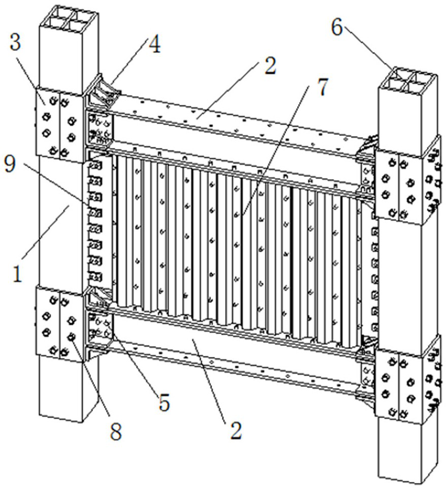
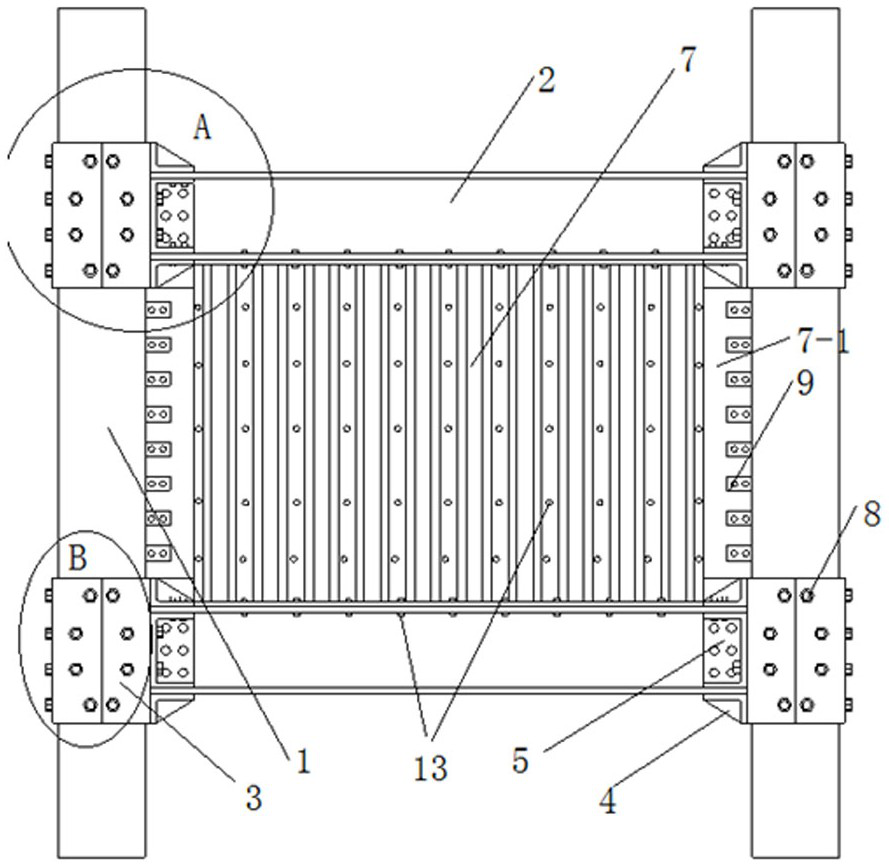
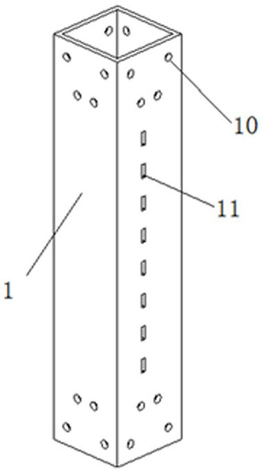
[0034] Such as figure 1 , 2 As shown, the energy dissipation system of a corrugated steel damping wall and concrete-filled steel tube column structure of the present invention includes several groups of energy-dissipating system monomers, and each group of energy-dissipating system monomers includes two concrete-filled steel tube columns 1 and a corrugated steel damping wall 7 and two I-beams 2, the concrete filled steel tube column 1 includes three hollow st...


PUM


Abstract

The invention discloses a wave-shaped steel damping wall and concrete filled steel tubular column structure energy dissipation system. The wave-shaped steel damping wall and concrete filled steel tubular column structure energy dissipation system comprises a wave-shaped steel damping wall and concrete filled steel tubular columns. Cross-shaped steel cores are arranged in hollow steel tubes, and concrete mortar is injected to form the concrete filled steel tubular columns; and the wave-shaped steel damping wall is formed by combining wave-shaped steel plates and energy dissipation inner core plates. The upper connecting end part and the lower connecting end part of the wave-shaped steel damping wall are connected with I-shaped steel beams through bolts, and the left connecting end part and the right connecting end part of the wave-shaped steel damping wall are connected with the concrete filled steel tubular columns through shear keys. The I-shaped steel beams are connected with the concrete filled steel tubular columns through web connecting pieces and flange connecting pieces. The damping wall surface adopts the two-side pressure wave type steel plates to cooperatively dissipate energy, the two-side pressure wave type steel plates are connected and combined into a row of embedded columns to support the upper-layer I-shaped steel beam to increase the stability of the whole structure, the energy dissipation inner core plates and the concrete filled steel tubular columns are connected through the shear keys, the energy dissipation inner core plates and the concrete filled steel tubular columns are linked to dissipate energy when vibration occurs, and the characteristic of reducing vibration energy is achieved.

Description

technical field [0001] The invention relates to the field of novel energy consumption and shock absorption of construction engineering, in particular to an energy consumption system of a corrugated steel damping wall and a steel pipe concrete column structure. Background technique [0002] The steel structure has superior seismic performance, has good ductility under earthquake action, and can absorb the energy exerted by the earthquake. Relatively speaking, the traditional prefabricated reinforced concrete structure is rigidly connected between the wall and the beam column. Due to the low seismic performance of the wall itself, it is prone to shear failure under the action of the earthquake. It has been proved that the prefabricated steel structure house after the earthquake The steel beam skeleton has not been damaged too much, but the reinforced concrete walls connected with the beams and columns are often damaged. Therefore, how to increase the energy consumption and sh...

Claims


Application Information

Patent Timeline
IPC IPC(8): E04B2/56E04B2/60E04C3/34E04B1/98E04H9/02
CPCE04B1/98E04B2/56E04B2/60E04C3/34E04H9/021
Inventor 王伽琪刘浩刘晓周博王兵李兵宗亮田立明
Owner 辽宁省中医药研究院
Why Eureka
Try Eureka