
Carbon fiber composite material rod joint

A composite material and rod joint technology, which is applied in the field of carbon fiber composite material rod joints, can solve problems such as lack of glue, affecting the connection strength of joints and composite material rods, and pressure applied by the glue layer, so as to achieve small assembly stress and high overall structural stability , the effect of uniform glue layer

Active Publication Date: 2020-03-17
CHANGCHUN INST OF OPTICS FINE MECHANICS & PHYSICS CHINESE ACAD OF SCI
View PDF6 Cites 0 Cited by
  • Summary
  • Abstract
  • Description
  • Claims
  • Application Information

AI Technical Summary

Problems solved by technology

[0003] The purpose of the present invention is to provide a carbon fiber composite material rod joint to solve the problem that in the prior art, because the bonding area of ​​the composite material rod and the bonding sleeve area of ​​the joint are an integral structure, the bonding process cannot exert pressure on the adhesive layer, and the sticking After the adhesive layer in the joint area is cured, there is a lack of adhesive bonding defect, which affects the technical problem of the connection strength between the joint and the composite material rod

Method used


Image

  • Carbon fiber composite material rod joint
  • Carbon fiber composite material rod joint
  • Carbon fiber composite material rod joint

Examples


Embodiment 1

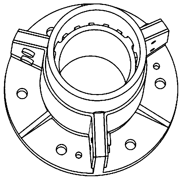
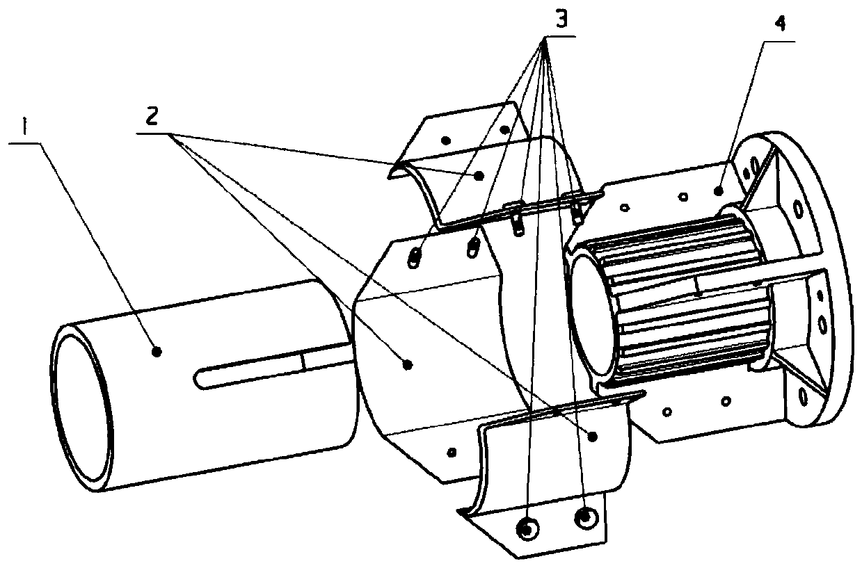
[0037] refer to Figure 1-7 , a carbon fiber composite material rod 1 joint, including a base 4, a force transmission tile 2, the base 4 includes a flange 4-1, a central cylinder 4-4 arranged on the flange 4-1, and a central cylinder symmetrically arranged 4-4 three radial partitions 4-3 of the outer wall,

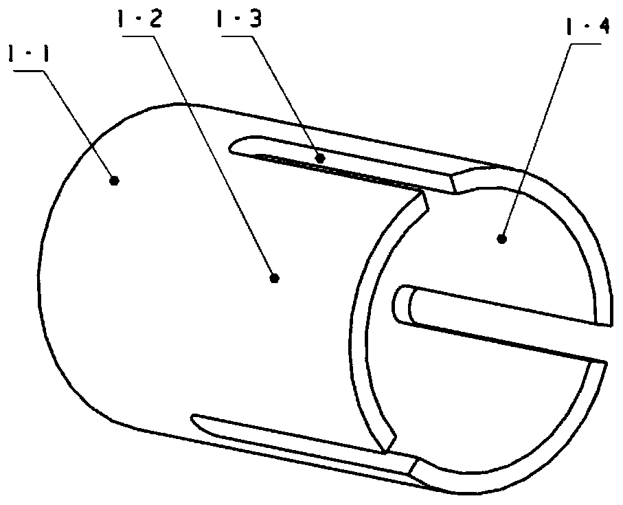
[0038] The composite material rod 1 is provided with three slots 1-3 that fit in clearance with the partition plate 4-3, and the three slots 1-3 are symmetrically distributed at 120° around the axis of the composite material rod 1, and the composite material rod 1 is The outer surface of the remaining part of the rod segment 1-1 cut by the groove 1-3 is the rod bonding area 1-2. The slot 1-3 of the composite material rod 1 passes through the partition plate 4-3, so that the positioning inner wall 1-4 of the composite material rod 1 is clearance-fitted with the outer wall of the central cylinder 4-4.

[0039] The force transmission tile 2 is a thin-walled structure, which...


PUM


Abstract

The invention provides a carbon fiber composite material rod joint. The joint comprises a base and force transmission tiles; the base comprises a flange, a central cylinder arranged on the flange andat least two radial partition plates symmetrically arranged on the outer wall of the central cylinder; a cutting groove in clearance fit with the partition plates is formed in a composite material rod; the cutting grooves penetrate through the partition plates, so that the inner wall of the composite material rod is in clearance fit with the outer wall of the central cylinder; the force transmission tiles are arranged between the two partition plates and used for extruding and fixing the composite material rod; and the number of the force transmission tiles is the same as that of the partitionplates. The composite material rod and the base are bonded into a whole through the separated force transmission tiles, a glue layer has adaptability to assembly stress in the bonding process, the assembly stress of the composite material rod and the base after curing is small, and the overall structural stability is high.

Description

technical field [0001] The invention relates to the field of aerospace structures, and more specifically, to a carbon fiber composite rod joint. Background technique [0002] Carbon fiber composite rods are widely used in the field of aerospace structures, especially low linear expansion carbon fiber composite rods, which are mostly used in the support structure of payloads that require high on-orbit thermal deformation indicators. The rods are connected and assembled with other parts through rod joints at both ends. Limited by the carbon fiber composite layer winding and demoulding process, the two ends of the composite rod cannot be directly made into a joint that is integrated with the rod, and the rod and the joint can only be fabricated separately and assembled into one. The traditional composite material rod joint is in the form of a sleeve. This type of joint is composed of a flange and a bonding sleeve area. The bonding sleeve area is a cylindrical surface that matc...

Claims


Application Information

Patent Timeline
IPC IPC(8): F16B7/08F16B7/04F16B7/20
CPCF16B7/042F16B7/20
Inventor 赵浩江薛闯董吉洪徐抒岩
Owner CHANGCHUN INST OF OPTICS FINE MECHANICS & PHYSICS CHINESE ACAD OF SCI
Learn More