Supercharge Your Innovation With Domain-Expert AI Agents!

Device for reducing wind load of wind turbine and wind turbine

A wind turbine and wind load technology, applied in the field of wind turbines, can solve the problems of increasing the wind load effect of a new tower structure, unfavorable social economy and safety, instability and collapse of the wind turbine, etc., so as to improve the overall stability and simple structure. , to avoid the effect of overall collapse

Active Publication Date: 2021-07-23
CEEC JIANGSU ELECTRIC POWER DESIGN INST
View PDF6 Cites 0 Cited by
  • Summary
  • Abstract
  • Description
  • Claims
  • Application Information

AI Technical Summary

Problems solved by technology

[0003] At present, increasing the size and wall thickness of the tower and changing the shape of the tower are one of the main solutions, but increasing the size and wall thickness of the tower will greatly increase the consumables. In addition, changing the shape of the tower also has many disadvantages, such as the need to make special-shaped formwork , which increases the difficulty of construction. The most serious thing is that because the tower does not change with the wind direction, the randomness of the wind direction will sometimes increase the wind load of the new tower structure, and even cause the wind turbine to lose its stability and collapse, which is harmful to the society. Economic and security adverse effects

Method used


Image

  • Device for reducing wind load of wind turbine and wind turbine
  • Device for reducing wind load of wind turbine and wind turbine
  • Device for reducing wind load of wind turbine and wind turbine

Examples


Embodiment 1

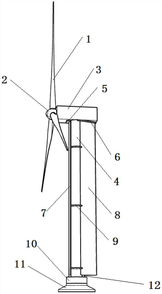
[0035] The invention provides a device for reducing the wind load of a wind turbine, please refer to figure 1 , including the windward plate 7, the wake guide plate 8 and the fixing seat 10, the windward plate 7, the wake guide plate 8 and the fixing seat 10 are arranged on the outer side of the wind turbine tower 4, the shape of the windward plate 7 and the tower tube 4 It is an arc-shaped plate, and the cross-section of the wake guide plate 8 is streamlined. The thicknesses of the windward plate 7 and the wake deflector 8 are the same, but it should be noted that those skilled in the art can set the thickness of the windward plate 7 to be greater than the thickness of the wake deflector 8, or set the thickness of the windward plate 7 to be greater than that of the wake deflector 8. The thickness is changed to be smaller than the thickness of the wake deflector 8 , in order to enable the windward plate 7 to be stably rotatably connected to the fixed seat 10 , the thickness of...

Embodiment 2

[0044] The present invention also provides a wind turbine, which adopts the device for reducing the wind load of the wind turbine described in the first embodiment.

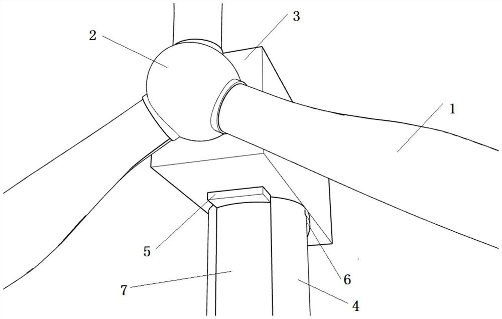
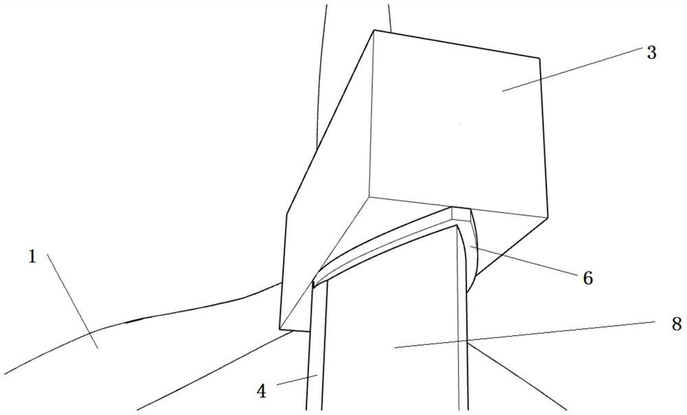
[0045] Specifically, the wind turbine is composed of a base 11, a tower 4 mounted on the base 11, and a main body of the wind turbine mounted on the tower 4. The main body of the wind turbine is a 3MW horizontal axis wind turbine. The main body of the machine includes blades 1, hub 2, and nacelle 3, and the device for reducing the wind load of the wind turbine includes a front connecting plate 5, a rear connecting plate 6, a windshield 7, a wake deflector 8, a reinforcement 9, and a fixing seat 10 and transition plate 12. There are three blades 1 with a length of 68.8m. The blades 1 are made of glass fiber reinforced epoxy resin and are installed on the hub 2. Each blade 1 is spaced at 120°. The hub 2 is made of steel, and its center height is 140m. The hub 2 is connected to the nacelle 3 at the end away from th...


PUM


Abstract

The invention discloses a device for reducing the wind load of a wind turbine and the wind turbine. The device comprises a windward plate, a wake flow guide plate and a fixing seat which are arranged at the outer side of a tower drum of the wind turbine, the windward plate is fixedly connected with the wake flow guide plate through a plurality of reinforcing pieces, the fixing seat is arranged on a reference seat of the wind turbine, and the windward plate is rotationally connected with the fixing seat. According to the device for reducing the wind load of the wind turbine and the wind turbine, the wind load of the wind turbine can be reduced, the tower drum is protected, the whole wind turbine is prevented from collapsing, and the service life of the wind turbine is prolonged.

Description

technical field [0001] The invention relates to a device for reducing the wind load of a wind turbine and the wind turbine, and belongs to the technical field of wind load reduction devices for the wind turbine. Background technique [0002] With the rapid development of the wind power industry, wind turbines have gradually become more powerful and towering, accompanied by the characteristics of large loads and ultra-high and thin towers. For such typical wind-sensitive structures, the wind turbine tower must ensure its rigidity, strength and stability without a large increase in consumables, and at the same time prevent the overall collapse of the wind turbine. Therefore, appropriate engineering structural measures are taken for wind turbines, and local thickening is carried out in places where the tower is easily damaged or may collapse, so as to reduce the loss of tower materials, and at the same time reduce the adverse effects of tail flow and vortex, thereby reducing th...

Claims


Application Information

Patent Timeline
Patent Type & Authority Applications(China)
IPC IPC(8): F03D1/06F03D13/20F03D80/00
CPCF03D1/0633F03D1/0675F03D13/20F03D80/00Y02E10/728Y02E10/72
Inventor 余文林卢红前彭秀芳袁万王曦鹏朱岩张宇施晨
Owner CEEC JIANGSU ELECTRIC POWER DESIGN INST
Features
  • R&D
  • Intellectual Property
  • Life Sciences
  • Materials
  • Tech Scout
  • Unparalleled Data Quality
  • Higher Quality Content
  • 60% Fewer Hallucinations
Learn More