
An electronic circuit board assembly piston drying air knife

An electronic circuit board and drying air technology, which is applied in the direction of drying gas arrangement, drying, drying machine, etc., can solve the problems such as the inability to control the air outlet pressure of the air knife more stably, increase the difficulty and cost of cleaning, and equipment pollution , to avoid polluting the surrounding air and equipment, improve rapid response capabilities, and reduce cleaning costs

Active Publication Date: 2022-07-15
东莞汇和电子有限公司
View PDF38 Cites 0 Cited by
  • Summary
  • Abstract
  • Description
  • Claims
  • Application Information

AI Technical Summary

Problems solved by technology

[0003] At present, the cross-sectional size of the air duct of the drying air knife is the same everywhere. When the high-pressure fan sends the air into the air knife through the duct, it blows to the air outlet, and the wind entering the air duct is unevenly distributed and the wind pressure is inconsistent. There is a large difference in wind pressure at both ends of the air duct, among which the wind pressure and wind speed at the air outlet near the air inlet are high, while the wind pressure and wind speed at the air outlet far from the air inlet are small, so the wind blown from the entire bar-shaped air outlet and Uneven wind speed leads to different drying speed of electronic circuit boards. Similarly, the pressure of the air outlet cannot be adjusted inside the air knife. control, limited
[0004] The conveyor belt carries the electronic circuit boards through the air knife in turn. After the high-speed airflow hits the electronic circuit board, it carries impurities and water and floats backwards. Part of it falls on the subsequent electronic circuit board, and the other part falls on the equipment, causing pollution to the equipment. Follow-up cleaning is required, which greatly increases the difficulty and cost of cleaning

Method used


Image

  • An electronic circuit board assembly piston drying air knife
  • An electronic circuit board assembly piston drying air knife
  • An electronic circuit board assembly piston drying air knife

Examples


Embodiment Construction

[0019] The technical solutions in the embodiments of the present invention will be clearly and completely described below with reference to the accompanying drawings in the embodiments of the present invention. Obviously, the described embodiments are only a part of the embodiments of the present invention, rather than all the embodiments. Based on the embodiments of the present invention, all other embodiments obtained by those of ordinary skill in the art without creative efforts shall fall within the protection scope of the present invention.

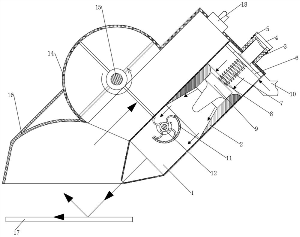
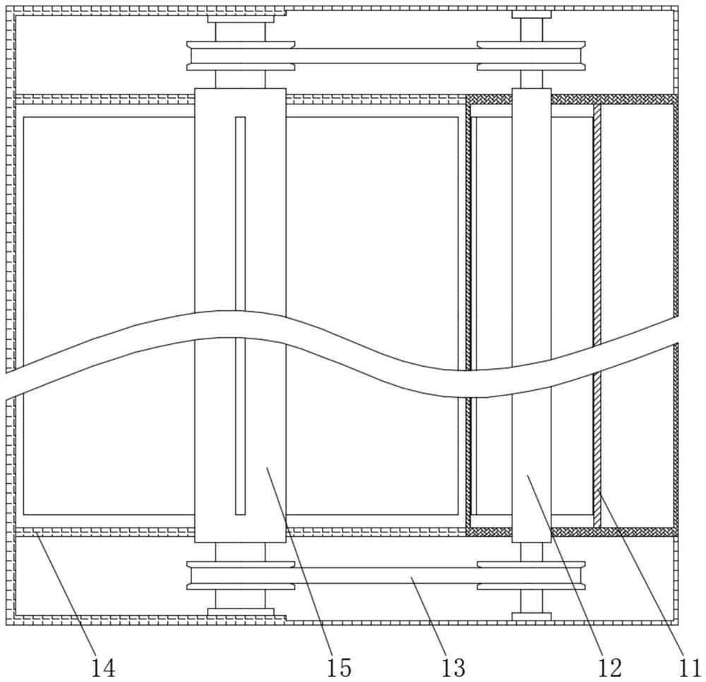
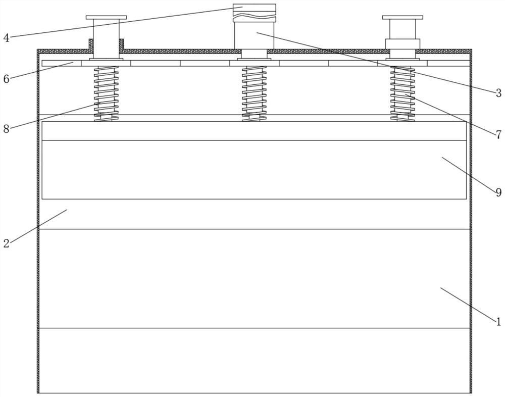
[0020] see Figure 1-4 , an electronic circuit board assembly piston drying air knife, including an air knife tube 1, an electronic circuit board 17 and a high-pressure fan. A rotating button 4 is connected, the bottom end of the rotating button 4 is fixedly connected with a sliding plate 6, the sliding plate 6 is movably connected with the inner cavity of the air knife tube 1, and the bottom surface of the sliding plate 6 is fixedly...


PUM


Abstract

The invention relates to the technical field of electronic circuit board assembly, and discloses an electronic circuit board assembly piston drying air knife, which includes an air knife tube, an electronic circuit board and a high-pressure fan, wherein two sides of the inner cavity of the air knife tube are fixedly installed with special shapes The clamping wall, the top end of the air knife tube is threadedly connected with a rotating button. Through the setting of the piston plate, after the gas enters from the air inlet pipe, it stays on the top of the piston plate for a short time. After the pressure is equalized, the piston plate is pressed down and released linearly to ensure that the pressure at the air outlet is the same, thereby ensuring the injection The same high-speed airflow pressure is used to improve the air-drying quality of the electronic circuit board. At the same time, through the setting of the spring and the rotary button, the height of the piston plate can be adjusted to adjust the pressure of the air when the air is ejected from the top of the piston plate. The air pressure from the air outlet improves the quick response ability of the air knife when it is working, and the pressure of the high-speed air flow can be adjusted in time according to the needs.

Description

technical field [0001] The invention relates to the technical field of electronic circuit board assembly, in particular to an electronic circuit board assembly piston drying air knife. Background technique [0002] At present, in the process of assembling electronic circuit boards, there is a process of cleaning the circuit boards. In order to speed up the assembly efficiency, it is necessary to use a drying air knife to air dry the circuit boards. The drying air knife used on the electronic circuit board is mainly used. After the air from the high-pressure fan enters the air knife, it is blown out at a high speed by an airflow sheet with a thickness of only 0.05 mm, and then the high-speed airflow impacts the electronic circuit board, collides with the water and impurities on it, impacts and carries it away, making the electronic circuit board fast Drying, but the existing drying air knife has some shortcomings, as follows: [0003] At present, the cross-sectional size of ...

Claims


Application Information

Patent Timeline
Patent Type & Authority Patents(China)
IPC IPC(8): F26B21/00
CPCF26B21/004
Inventor 不公告发明人
Owner 东莞汇和电子有限公司
Learn More