
GIS bus residual voltage measuring device and calculation method based on electric field

A technology of residual voltage and measuring device, applied in the direction of measuring device, measuring current/voltage, measuring electric variable, etc., can solve the problems of flashover, affecting the insulation level of gas-insulated switchgear, and reducing the insulation level of busbars.

Pending Publication Date: 2021-07-23
ELECTRIC POWER RES INST OF STATE GRID ANHUI ELECTRIC POWER +1
View PDF0 Cites 1 Cited by
  • Summary
  • Abstract
  • Description
  • Claims
  • Application Information

AI Technical Summary

Problems solved by technology

For example, in my country's UHV AC substations, the failure of the basin insulator in the combination switch caused by switching the gas-insulated combination switch during the start-up and commissioning process occurred. When the metal particles accumulate on the surface, the insulation level of the GIS busbar decreases, and the operation overvoltage is caused by superimposed closing.
GIS busbar residual voltage level and decay time and other characteristics will have an impact on GIS busbar insulation. The longer and longer the residual voltage of the GIS bus leads to higher and higher residual voltage, which seriously affects the insulation level of the gas-insulated combination switch. The traditional VFTO measuring device installed on the GIS bus cannot realize the measurement of DC voltage. Therefore, it is necessary to measure the DC residual voltage of the GIS bus. Conduct research on voltage measurements

Method used


Image

  • GIS bus residual voltage measuring device and calculation method based on electric field
  • GIS bus residual voltage measuring device and calculation method based on electric field
  • GIS bus residual voltage measuring device and calculation method based on electric field

Examples


Embodiment Construction

[0052] The following will clearly and completely describe the technical solutions in the embodiments of the present invention with reference to the accompanying drawings in the embodiments of the present invention. Obviously, the described embodiments are only some, not all, embodiments of the present invention. Based on the embodiments of the present invention, all other embodiments obtained by persons of ordinary skill in the art without making creative efforts belong to the protection scope of the present invention.

[0053] In the description of this embodiment, it should be noted that the terms "connect" and "place" should be understood in a broad sense, for example, "connect" can be a wire connection or a mechanical connection; "place" can be a fixed connection placement, also can be one-piece placement. Those of ordinary skill in the art can understand the specific meanings of the above terms in this embodiment according to specific situations.

[0054] GIS busbar resi...


PUM


Abstract

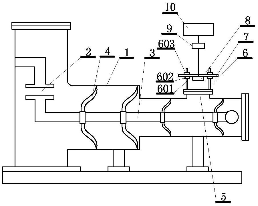
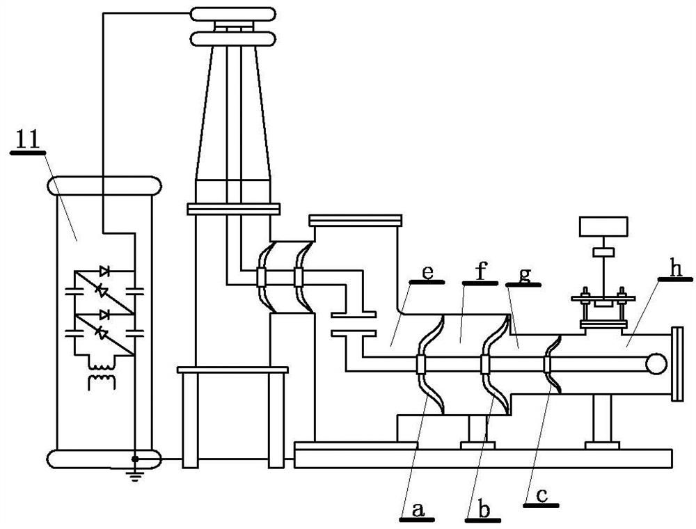
The invention discloses a GIS bus residual voltage measuring device and calculation method based on an electric field. The measuring device comprises a sealed tank body surrounding a GIS bus; the GIS bus is supported in the tank body through an insulator; the tank body is filled with SF6 insulating gas; the tank body is provided with a visual observation window; the visual observation window is connected with a grounding metal plate through a supporting frame; an electric field space is formed between the lower end face of the grounding metal plate and the GIS bus through the observation window; and the lower end face of the grounding metal plate is fixedly provided with a field intensity meter which is connected with a voltage display. With the GIS bus residual voltage measuring device and calculation method based on the electric field of the invention adopted, the problem of measurement and calculation of the residual voltage of the GIS bus after the switching off of a gas insulation combination switch can be solved. The GIS bus residual voltage measuring device and calculation method based on the electric field can adapt to measurement of the residual voltage of the GIS bus in different amplitude ranges by adjusting the distance between the grounding metal plate and the GIS bus and calibrating the voltage of the GIS bus, and are different from a measuring method based on resistance voltage division and capacitance coupling.

Description

technical field [0001] The invention relates to an electric field-based GIS busbar residual voltage measurement device and a calculation method thereof. Background technique [0002] Gas insulated switchgear (GIS, gas insulated switchgear) has significant advantages such as small footprint, less environmental impact, less maintenance workload, high operational reliability, and low operating cost, and has been widely used in power systems. [0003] When the UHV substation switches the gas-insulated combination switch, the GIS bus in the combination switch will generate residual voltage. The DC property of the residual voltage makes the influence of particle movement and electric field distribution different from that of AC. For example, in my country's UHV AC substations, the failure of the basin insulator in the combination switch caused by switching the gas-insulated combination switch during the start-up and commissioning process occurred. When the metal particles accumula...

Claims


Application Information

Patent Timeline
Patent Type & Authority Applications(China)
IPC IPC(8): G01R19/00
CPCG01R19/00
Inventor 程登峰傅中秦金飞姜奎夏令志刘宇舜程洋李森林赵玉顺
Owner ELECTRIC POWER RES INST OF STATE GRID ANHUI ELECTRIC POWER
Learn More