Eureka AIR delivers breakthrough ideas for toughest innovation challenges, trusted by R&D personnel around the world.

Diffraction waveguide device, near-eye display equipment and manufacturing method

A near-eye display and diffracted wave technology, which is applied in light guides, instruments, optics, etc., can solve the problems of low utilization rate of waveguide substrate, small setting area of ​​outcoupling grating, and reduction of effective outcoupling grating area, so as to improve the utilization rate of grating , Increase the effect of the effective display area

Pending Publication Date: 2021-07-23
GUANGDONG OPPO MOBILE TELECOMM CORP LTD
View PDF0 Cites 20 Cited by
  • Summary
  • Abstract
  • Description
  • Claims
  • Application Information

AI Technical Summary

Problems solved by technology

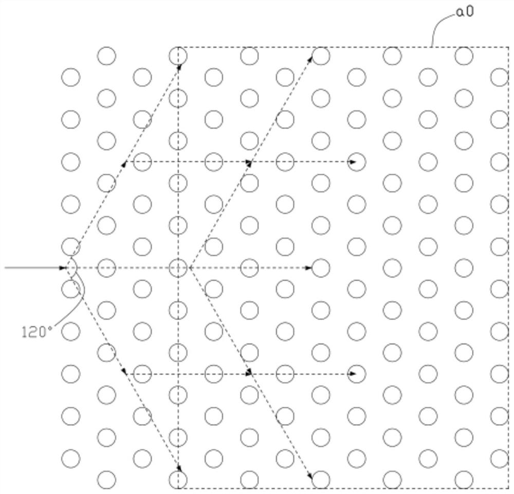
[0003] However, the above-mentioned first type of diffractive waveguide system needs to occupy the area of ​​the waveguide substrate because the deflection grating needs to occupy the area of ​​the waveguide substrate, so the installation area of ​​the outcoupling grating is small, which makes the utilization rate of the waveguide substrate low, thereby limiting the eye movement range (Eye Box); figure 1 As shown, the existing two-dimensional grating in the above-mentioned second type of diffraction waveguide system mainly uses a periodic structure of hexagonal lattice, and the pupil expansion angle of the periodic structure is 120°. Therefore, a part of the grating area is required for pupil expansion. which is figure 1 The dotted box a0 in the figure represents the effective outcoupling grating area, and the grating on the left side of the dotted box a0 is an ineffective outcoupling grating for pupil expansion, resulting in a decrease in the effective outcoupling grating area

Method used


Image

  • Diffraction waveguide device, near-eye display equipment and manufacturing method
  • Diffraction waveguide device, near-eye display equipment and manufacturing method
  • Diffraction waveguide device, near-eye display equipment and manufacturing method

Examples


Embodiment Construction

[0053] The technical solutions in the embodiments of the application will be clearly and completely described below in conjunction with the accompanying drawings in the embodiments of the application. Obviously, the described embodiments are only part of the embodiments of the application, not all of them. Based on the implementation manners in this application, all other implementation manners obtained by persons of ordinary skill in the art without making creative efforts belong to the scope of protection of this application.

[0054]It should be noted that referring to "embodiment" or "implementation" herein means that specific features, structures or characteristics described in conjunction with the embodiment or implementation may be included in at least one embodiment of the present application. The occurrences of this phrase in various places in the specification are not necessarily all referring to the same embodiment, nor are separate or alternative embodiments mutuall...


PUM


Abstract

The invention provides a diffraction waveguide device, which comprises a waveguide substrate and a grating structure; the grating structure is arranged on the surface of the waveguide substrate and comprises a plurality of grating units; the plurality of grating units have a first period in a first direction and a second period in a second direction different from the first direction, and the two-dimensional pupil expansion angle of the grating structure is 180 degrees by adjusting the first period and the second period. The effective coupling-out grating area of the grating structure is rectangular, so that the grating structure is only used for pupil expansion without partial grating units, the effective coupling-out area of the grating units of the grating structure is increased, the effective display area of the grating structure is increased, and the grating utilization rate is improved. The invention further provides near-eye display equipment provided with the diffraction waveguide device and a manufacturing method of the diffraction waveguide device.

Description

technical field [0001] The present application relates to the technical field of diffractive optical devices, in particular to a diffractive optical waveguide device, a near-eye display device provided with the diffractive optical waveguide device, and a manufacturing method of the diffractive optical waveguide device. Background technique [0002] With the development of technology, augmented reality (Augmented Reality, AR) display devices, such as AR glasses, can not only see the external real world but also need to see virtual images. Near-eye display devices usually include a diffraction waveguide system. There are two types of grating-based diffraction waveguide systems. The first type is a diffraction waveguide system with three or more one-dimensional grating regions; the second type is a two-dimensional diffraction waveguide system with two grating regions. waveguide system. The first type of diffractive waveguide system includes a waveguide substrate, an in-couplin...

Claims


Application Information

Patent Timeline
Patent Type & Authority Applications(China)
IPC IPC(8): G02B6/124G02B27/01
CPCG02B6/124G02B27/0101G02B2027/0123G02B27/0172G02B27/01G02B27/0081G02B6/34
Inventor 郑光
Owner GUANGDONG OPPO MOBILE TELECOMM CORP LTD
Why Eureka
Eureka Blog
Learn More