Coarse mesh-based rapid turbulence wall surface function aerodynamic force prediction method

A prediction method and coarse grid technology, applied in the direction of electrical digital data processing, CAD numerical modeling, special data processing applications, etc., can solve the problems of excessive computer internal resources and slow calculation convergence speed, so as to improve calculation efficiency, Reduced workload and high calculation accuracy

Active Publication Date: 2021-07-23
CALCULATION AERODYNAMICS INST CHINA AERODYNAMICS RES & DEV CENT
View PDF2 Cites 8 Cited by
  • Summary
  • Abstract
  • Description
  • Claims
  • Application Information

AI Technical Summary

Problems solved by technology

[0003] In order to overcome the deficiencies of the prior art, the present invention provides a method for predicting the aerodynamic force of the rapid turbulent wall function based on the coarse grid, which solves the calculation convergence ca

Method used


Image

  • Coarse mesh-based rapid turbulence wall surface function aerodynamic force prediction method
  • Coarse mesh-based rapid turbulence wall surface function aerodynamic force prediction method
  • Coarse mesh-based rapid turbulence wall surface function aerodynamic force prediction method

Examples


Embodiment 1

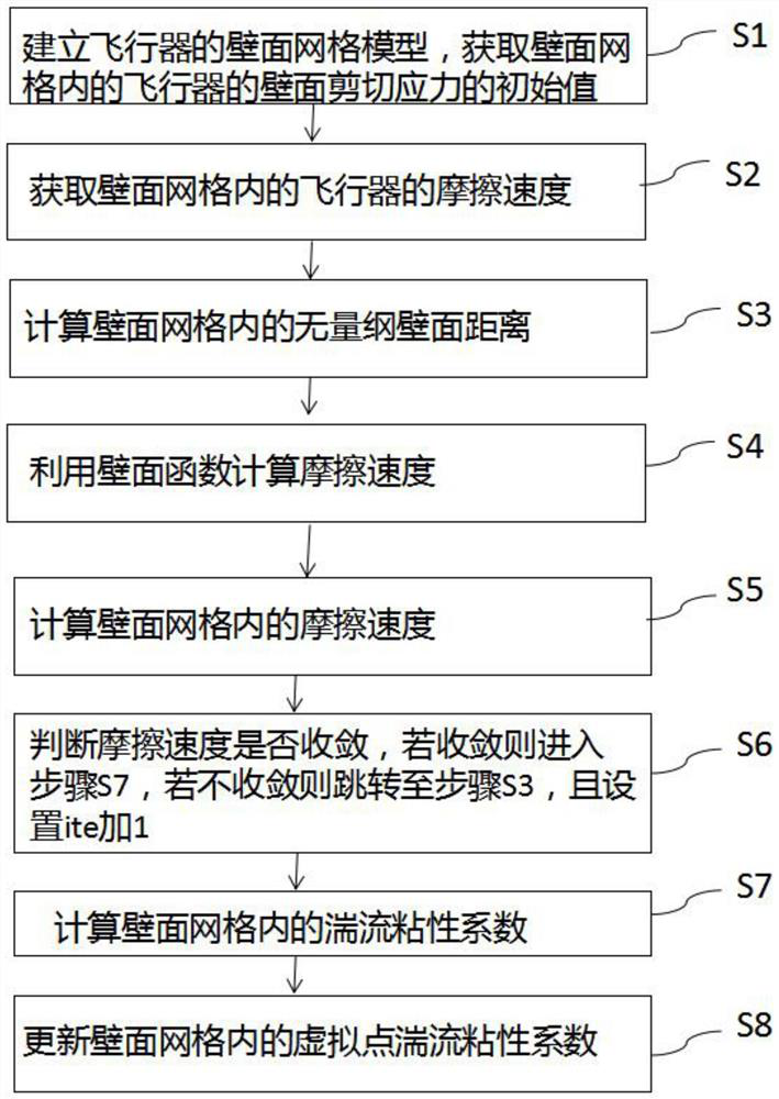
[0063] Such as Figure 1 to Figure 8 As shown, a method for predicting the aerodynamic forces of fast turbulent wall functions based on coarse grids includes the following steps:

[0064] S1, establish the wall mesh model of the aircraft, and obtain the initial value of the wall shear stress of the aircraft in the wall mesh, the formula is:

[0065]

[0066] Among them, τ is the shear stress, τ w is the wall shear stress, μ w is the wall molecular viscosity coefficient, μt is the turbulent flow viscosity coefficient, U is the inner wall parallel velocity of the wall grid, y is the wall distance, is the sign of the partial derivative, is the partial derivative of the wall parallel velocity in the wall normal direction in the wall grid, U P is the velocity of grid points on the wall;

[0067] S2, get the friction velocity U of the aircraft in the wall grid τ , whose formula is:

[0068]

[0069] Among them, ρ w is the wall density;

[0070] S3, calculate the dim...

Embodiment 2

[0109] Such as Figure 1 to Figure 8 As shown, this embodiment is based on Embodiment 1, reflecting the technical effect of adopting the present invention.

[0110] This technology uses the wall function based on the analytical velocity distribution in the wall coarse grid, and obtains the friction velocity through constructor iteration, which can effectively improve the prediction accuracy of the wall coarse grid, and with the increase of the wall grid distance, the grid volume The overall reduction can significantly save computing time and computing memory.

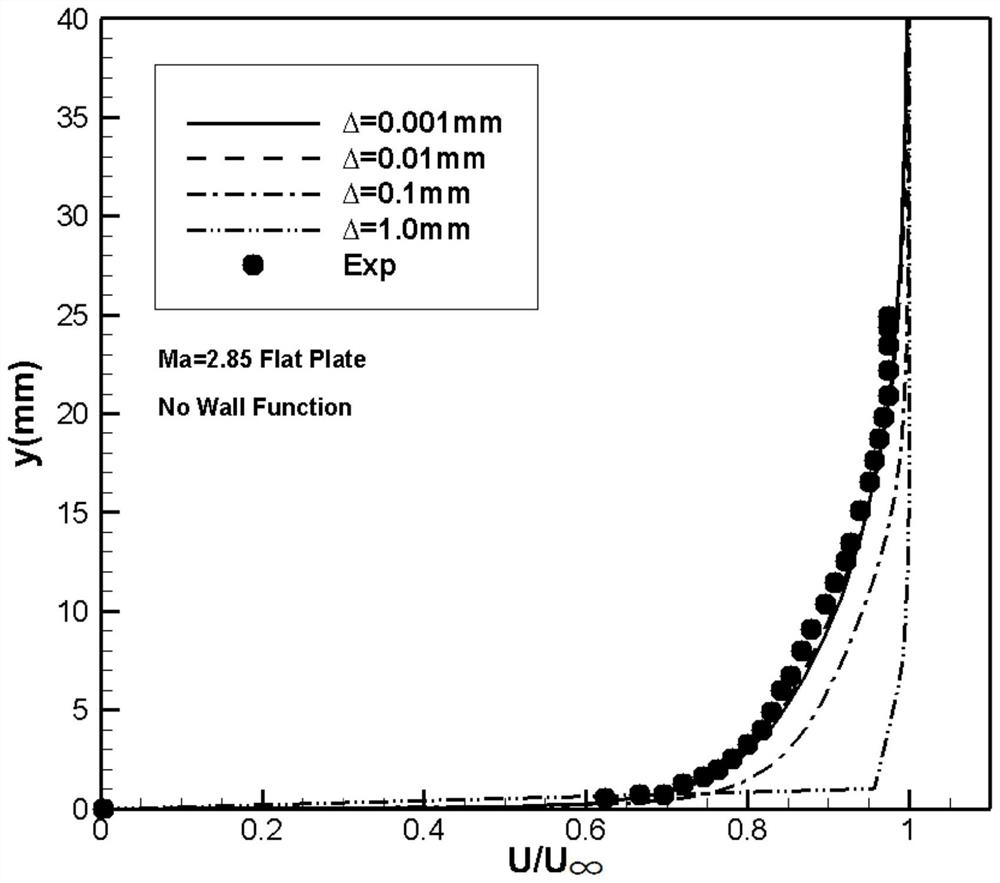
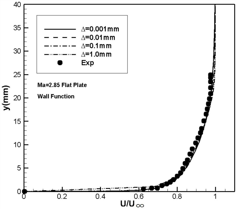
[0111] figure 2 , image 3 is the boundary layer velocity distribution of the hyper-slab turbulent flow with incoming flow Ma=2.85, when the wall function is not used ( figure 2 ), the numerical results of the coarse grid, the results of the dense grid, and the experimental results have large deviations, and the accuracy becomes worse with the increase of the grid wall distance, while image 3 After using the wall...


PUM


Abstract

The invention discloses a coarse mesh-based rapid turbulence wall surface function aerodynamic force prediction method, which comprises the following steps of S1, establishing a wall surface mesh model of an aircraft, and obtaining an initial value of wall surface shear stress of the aircraft in a wall surface mesh; s2, acquiring the friction speed of the aircraft in the wall grid; S3, calculating a dimensionless wall surface distance in the wall surface mesh; S4, calculating the friction speed in the wall surface mesh; S5, calculating a residual error; S6, judging whether the friction speed is converged or not; S7, calculating a turbulence viscosity coefficient in the wall surface mesh; and S8, updating the turbulence viscosity coefficient of the virtual points in the wall surface mesh. The invention solves the problems that in the prior art, when engineering complex turbulent flow is simulated, due to the fact that meshes near a wall face suddenly increase, the calculation convergence speed is reduced, many internal resources of a computer are occupied, and the numerical value rigidity problem is serious.

Description

technical field [0001] The invention relates to the technical field of computational fluid dynamics Reynolds average turbulence numerical simulation, in particular to a method for predicting the aerodynamic force of a fast turbulent wall function based on a coarse grid. Background technique [0002] Numerical simulation of turbulence is widely used in the design of hypersonic vehicles and the integrated design of propulsion systems. , inner runner, etc.) and aircraft trajectory optimization provide better research support, which play a very important role in practical applications and have strong practical significance. At present, RANS methods that consume less computing resources are mostly used at present. For the SST k-ω model commonly used in engineering, if it is necessary to accurately simulate wall friction and heat flow, the wall mesh is required to be dense enough, usually y+≈1, which will lead to a sudden increase in the mesh near the wall when simulating complex...

Claims


Application Information

Patent Timeline
IPC IPC(8): G06F30/15G06F30/28G06F111/10G06F113/08G06F119/14
CPCG06F30/15G06F30/28G06F2111/10G06F2113/08G06F2119/14Y02T90/00
Inventor 王新光何琨陈坚强毛枚良陈琦万钊张毅峰江定武郭勇颜张爱婧
Owner CALCULATION AERODYNAMICS INST CHINA AERODYNAMICS RES & DEV CENT
Why Eureka
Try Eureka