Wearable fabric antenna applied to WLAN

An antenna and fabric technology, which is applied in the field of fabric wearable antennas and wearable antennas, can solve the problems of inapplicability, narrow impedance bandwidth, etc., and achieve the effects of easy manufacture, easy integration, and low cost

Pending Publication Date: 2021-07-23
JIANGSU VOCATIONAL INST OF ARCHITECTURAL TECH
View PDF0 Cites 1 Cited by
  • Summary
  • Abstract
  • Description
  • Claims
  • Application Information

AI Technical Summary

Problems solved by technology

However, since the HMSIC antenna has a single resonance mode, its impedance bandwidth is very narrow and cannot be applied to higher transmission requirements

Method used


Image

  • Wearable fabric antenna applied to WLAN
  • Wearable fabric antenna applied to WLAN
  • Wearable fabric antenna applied to WLAN

Examples


Embodiment Construction

[0028] Below in conjunction with accompanying drawing, the present invention will be further described (left, right, front and rear directions and figure 1 The left, right, front and back directions in are the same, just to describe the present invention).

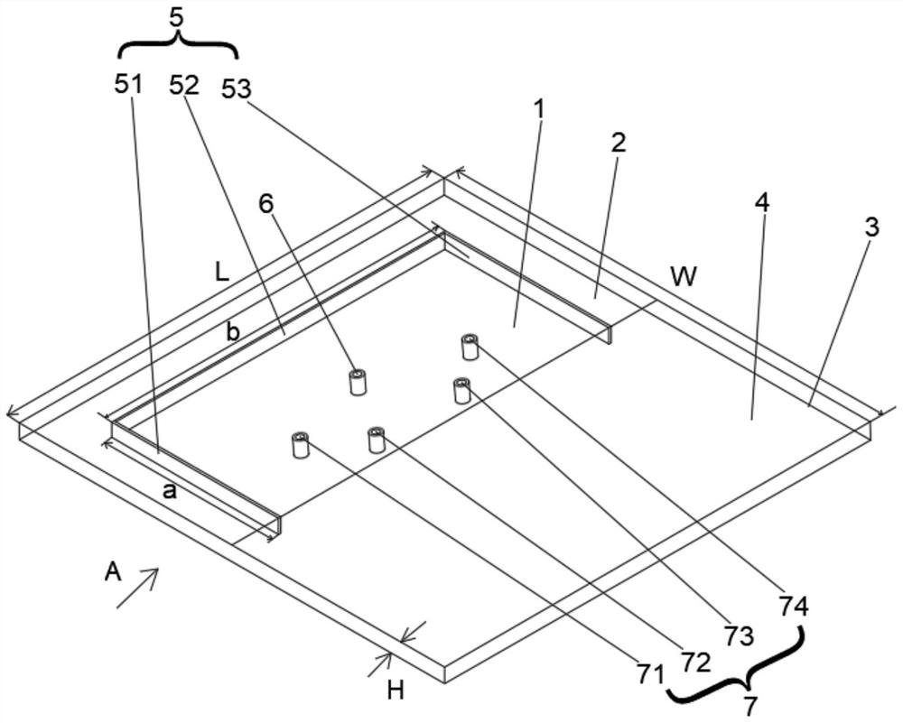
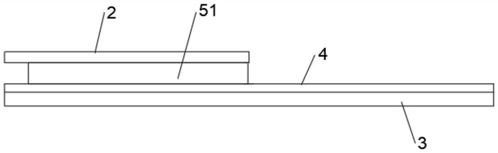
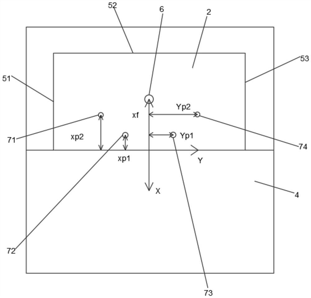
[0029] like Figure 1 to Figure 3 As shown, a fabric wearable antenna applied to WLAN includes a bottom surface 3, a top surface 2, a dielectric substrate 4, a conductive side wall 5, a feeding probe 6 and a metal copper column 7;

[0030] The size of the top surface 2 is half of the size of the bottom surface 3, and is located directly above the front half of the bottom surface 3;

[0031] The dielectric substrate 4 covers the upper surface of the bottom surface 3; the conductive sidewall 5 is composed of a left side conductive sidewall 51, a front side conductive sidewall 52 and a right side conductive sidewall 53 with the same height. The left side conductive side wall 51 and the right side conductive side wall 53 are...


PUM


Abstract

The invention discloses a wearable fabric antenna applied to a WLAN. According to the wearable fabric antenna, a top surface is located right above the front half part of a bottom surface; a dielectric substrate covers the bottom surface; a conductive side wall consists of a left conductive side wall, a front conductive side wall and a right conductive side wall; the left conductive side wall and the right conductive side wall are respectively connected to the left part and the right part of the upper surface of the dielectric substrate; the front conductive side wall is connected to the front part of the upper surface of the dielectric substrate, and two ends of the front conductive side wall are respectively connected with the front ends of the left conductive side wall and the right conductive side wall; the top surface is connected with the upper end of the conductive side wall and defines a cavity together with the dielectric substrate and the conductive side wall; the lower end of a feed probe is in insulated connection with the upper surface of the dielectric substrate, and the upper end of the feed probe is connected with the top surface; metal copper columns are composed of a left front metal copper column, a left rear metal copper column, a right rear metal copper column and a right front metal copper column, the left rear metal copper column and the right rear metal copper column are located on the rear portion of the middle part of the cavity, and the left front metal copper column and the right front metal copper column are located in the middle of the cavity; and the metal copper columns are respectively connected with the bottom surface and the top surface. The antenna of the invention is simple in structure, small in size and wide in bandwidth.

Description

technical field [0001] The invention relates to a wearable antenna, in particular to a fabric wearable antenna applied to WLAN, and belongs to the technical field of wireless communication. Background technique [0002] With the rapid development of mobile communications, wearable devices have been widely used in wireless local area network (WLAN) applications, such as health monitoring, physical exercise, emergency rescue services, and daily care for children and the elderly. Antennas are an important part of wearable devices and play a vital role in smart monitoring terminals. [0003] Compared with traditional antennas, wearable antennas need to pay more attention to comfort and robustness, and fabric antennas are ideal for wearable antenna designs. In the prior art, how to place a fabric antenna on the human body is an urgent problem to be solved. Firstly, the antenna must be designed with a low profile so that it can be integrated into clothes; secondly, it must be eas...

Claims


Application Information

Patent Timeline
Patent Type & Authority Applications(China)
IPC IPC(8): H01Q1/27H01Q1/36H01Q1/50
CPCH01Q1/273H01Q1/364H01Q1/50
Inventor 崔洁刘逢雪赵雷尹洪胜
Owner JIANGSU VOCATIONAL INST OF ARCHITECTURAL TECH
Why Eureka
Try Eureka