Pull-in type cable explosion-proof box

An explosion-proof box, pull-in technology, applied in the direction of cable joints, cable inlet sealing devices, etc., can solve the problems of cable insulation and drop cable breakdown, cable water and moisture, etc., to achieve reliable design principles, prevent water ingress, and meet waterproof requirements Anti-explosion effect

Pending Publication Date: 2021-07-23
STATE GRID SHANDONG ELECTRIC POWER CO QINGZHOU POWER SUPPLY CO +2
View PDF4 Cites 0 Cited by
  • Summary
  • Abstract
  • Description
  • Claims
  • Application Information

AI Technical Summary

Problems solved by technology

[0006] Aiming at the defect that the cables in the above-mentioned explosion-proof boxes in the prior art are affected by water and damp, which causes the cable insulation pair to decrease and cause cable breakdown, the present invention provides a suction-type cable explosion-proof box to solve the problems in the prior art

Method used


Image

  • Pull-in type cable explosion-proof box
  • Pull-in type cable explosion-proof box
  • Pull-in type cable explosion-proof box

Examples


Embodiment 1

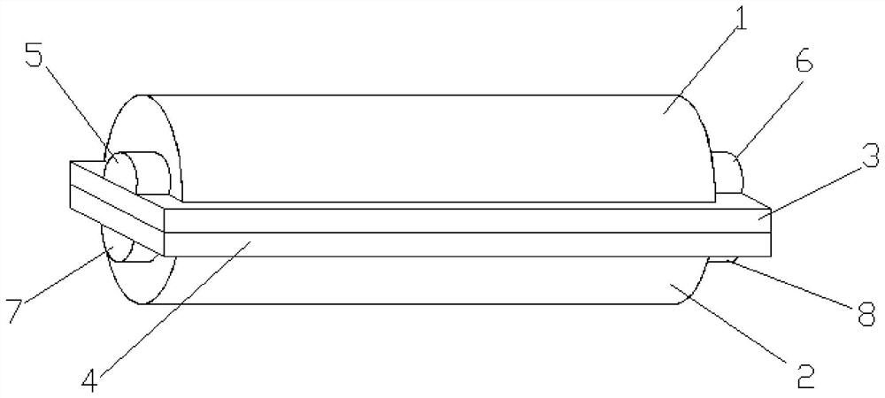
[0047] Such as figure 1 , figure 2 , image 3 and Figure 4 As shown, the present invention provides a suction-type cable explosion-proof box, comprising an upper explosion-proof shell 1 and a lower explosion-proof shell 2;

[0048] Both the upper explosion-proof shell 1 and the lower explosion-proof shell 2 are made of flexible waterproof material;

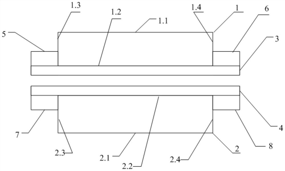
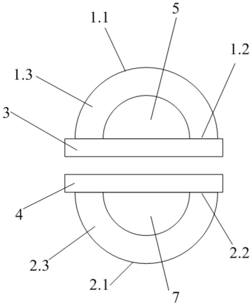
[0049] The upper explosion-proof shell 1 includes an upper arc explosion-proof surface 1.1, an upper rectangular fitting surface 1.2, a first upper semicircular end surface 1.3 and a second upper semicircular end surface 1.4; the first upper semicircular end surface 1.3 and the second upper semicircular end surface 1.4 are arranged on the upper arc The two ends of the rectangular explosion-proof surface 1.1 are connected to the upper rectangular fitting surface 1.2 to form a solid semi-cylindrical upper explosion-proof shell;

[0050] The lower explosion-proof shell 2 includes a lower arc-shaped explosion-proof surface 2.1, ...

Embodiment 2

[0056] Such as figure 1 , figure 2 , image 3 and Figure 4 As shown, the present invention provides a suction-type cable explosion-proof box, an upper explosion-proof shell 1 and a lower explosion-proof shell 2;

[0057] The upper explosion-proof shell 1 and the lower explosion-proof shell 2 are made of flexible waterproof material; the upper explosion-proof shell 1 and the lower explosion-proof shell 2 are made of hydrophobic silicone material;

[0058] The upper explosion-proof shell 1 includes an upper arc explosion-proof surface 1.1, an upper rectangular fitting surface 1.2, a first upper semicircular end surface 1.3 and a second upper semicircular end surface 1.4; the first upper semicircular end surface 1.3 and the second upper semicircular end surface 1.4 are arranged on the upper arc The two ends of the rectangular explosion-proof surface 1.1 are connected to the upper rectangular fitting surface 1.2 to form a solid semi-cylindrical upper explosion-proof shell;

...


PUM


Abstract

The invention provides a pull-in type cable explosion-proof box. The pull-in type cable explosion-proof box comprises an upper explosion-proof shell and a lower explosion-proof shell; the upper explosion-proof shell and the lower explosion-proof shell are solid semi-cylinders; the outer sides of the upper and lower rectangular binding surfaces are respectively provided with upper and lower cover magnetic layers, and the upper and lower explosion-proof shells are attracted through the upper and lower cover magnetic layers to form a cylindrical shape; two ends of the upper explosion-proof shell and the lower explosion-proof shell are respectively provided with a flexible sealing assembly; and a cable penetrating pipe extrudes and penetrates through the upper and lower flexible sealing assemblies and the joint of the upper cover magnetic layer and the lower cover magnetic layer, and a first sealing cavity, a penetrating pipe containing cavity and a second sealing cavity are formed in sequence. The pull-in type cable explosion-proof box provided by the invention meets the waterproof and explosion-flashover-proof requirements of a power cable, effectively prevents water from entering the cable through a pipe, avoids the flash explosion caused by the cable being affected with damp, and guarantees the safe operation of a power distribution network.

Description

technical field [0001] The invention belongs to the technical field of electric power equipment construction, and in particular relates to a suction-type cable explosion-proof box. Background technique [0002] The cable conduit is used to protect the cable, and can distinguish the function of the cable, which is convenient for wiring and maintenance. [0003] According to the power cable laying construction requirements, the intermediate joint of the power cable must be connected to the explosion-proof box, which protects the power cable and prevents the accident caused by the flash explosion of the cable. The two ends of the cable pipes need to be sealed to prevent the insulation of the power cables from being reduced due to water ingress, thereby affecting the safety of the distribution network. [0004] In the operation and maintenance of power cables laid into the ground, due to the limitations of construction technology and plugging materials, water leakage often occu...

Claims


Application Information

Patent Timeline
Patent Type & Authority Applications(China)
IPC IPC(8): H02G15/10H02G15/013
CPCH02G15/10H02G15/013
Inventor 郝建园文向东张郅业李丰硕孙华忠张跃勇陈允营葛亮彭鹏郭红军刘帅杨茂波刘静赵爽刘晓刘琴徐子华王斐凯公政张吉春李霖贾克军类金王鑫周轮王洪林孔令京王环张洪波陈复东刘序坤王建刚王宝龙
Owner STATE GRID SHANDONG ELECTRIC POWER CO QINGZHOU POWER SUPPLY CO
Why Eureka
Try Eureka