Intelligent gas burner ignition system

A gas burner and ignition system technology, which is applied in the direction of combustion ignition, combustion method, fire rescue, etc., can solve problems such as incomplete purging, personal safety hazards of operators, and leakage of combustible gas, so as to avoid equipment damage and casualties , Eliminate potential safety hazards and improve safety

Active Publication Date: 2022-01-11
上海轻叶能源股份有限公司
View PDF14 Cites 0 Cited by
  • Summary
  • Abstract
  • Description
  • Claims
  • Application Information

AI Technical Summary

Problems solved by technology

[0004] 1. Incomplete purging before starting the gas furnace leads to explosive mixture in the gas furnace combustion chamber after the gas furnace is ignited
[0005] 2. Too little combustion-supporting air leads to incomplete combustion, so that combustible gas accumulates in the combustion chamber or forms an explosive mixture after combustion
[0006] 3. The liquid brought out of the fuel gas-liquid separation tank will cause the flame to be unstable when the combustion furnace is ignited, and the liquid in the combustion chamber will cause the liquid in the combustion chamber to implode or burn the equipment over temperature
[0008] 5. Fuel gas enters the furnace area pipe network. Due to the complexity of the pipe network, seal leakage, various valves, flanges, and pipelines are scattered, the leakage of combustible gas generated, entering the furnace and encountering an open flame ignites the furnace area to explode
[0009] 6. Due to the long opening time of the gas shut-off valve, the fuel gas pressure of the igniter, flame sensor, and valve position feedback device does not meet the specified standards, resulting in a mismatch, resulting in ignition failure, or flammable gas release due to prolonged time
[0010] 7. Leakage of the gas valve causes the gas furnace to accumulate combustible gas and cause ignition and implosion
[0012] Due to the current conventional burner ignition operation or the use of PLC program control, none of the above-mentioned 8 risk factors can be overcome, resulting in safety accidents, and even returning to the previous backward manual ignition, resulting in long operation time and high labor intensity. Artificial ignition with naked flames has dangerous consequences for the personal safety of operators

Method used


Image

  • Intelligent gas burner ignition system
  • Intelligent gas burner ignition system
  • Intelligent gas burner ignition system

Examples


Embodiment Construction

[0034] The following will clearly and completely describe the technical solutions in the embodiments of the present invention with reference to the accompanying drawings in the embodiments of the present invention. Obviously, the described embodiments are only some, not all, embodiments of the present invention. Based on the embodiments of the present invention, all other embodiments obtained by persons of ordinary skill in the art without making creative efforts belong to the protection scope of the present invention.

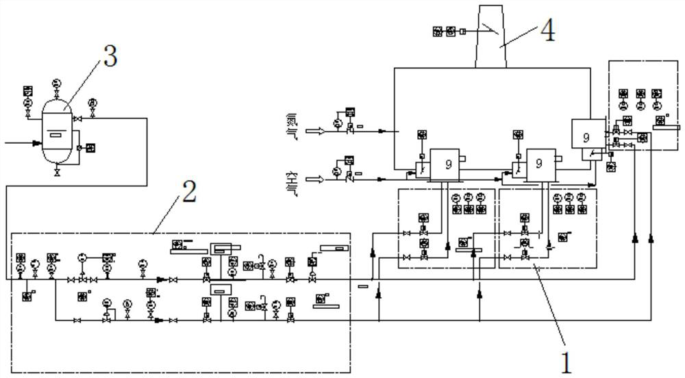
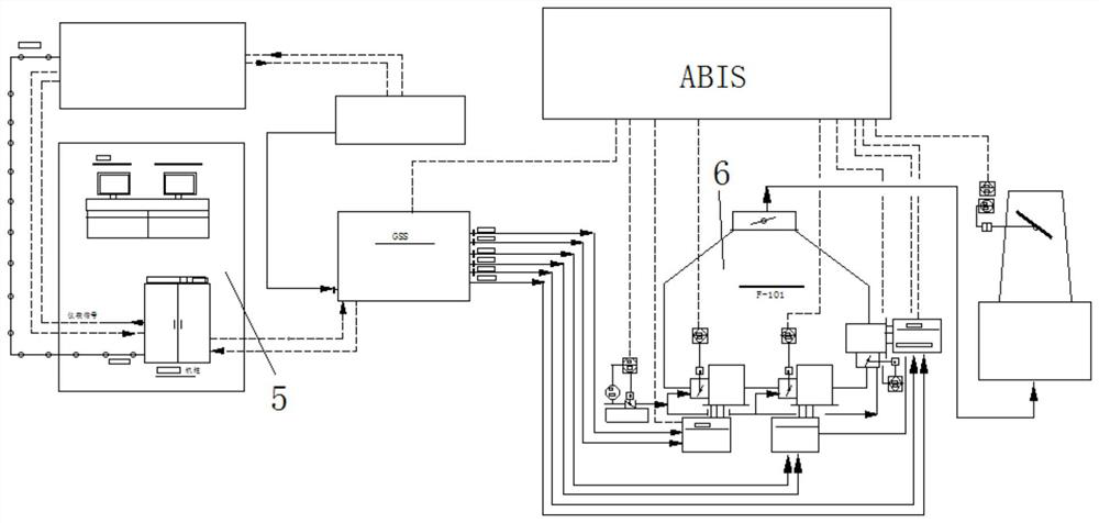
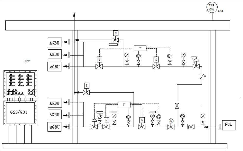
[0035] The purpose of the present invention is to provide an intelligent gas burner ignition system to solve the above-mentioned problems in the prior art, improve the efficiency of ignition, and improve the safety of the ignition process.

[0036] In order to make the above objects, features and advantages of the present invention more comprehensible, the present invention will be further described in detail below in conjunction with the accompanying drawings ...


PUM


Abstract

The invention discloses an intelligent gas burner ignition system, and relates to the technical field of burner ignition devices. The intelligent gas burner ignition system comprises a burner ignition part which is skid-mounted in one closed device and a fuel gas conveying part which is skid-mounted in the other closed device. The burner ignition part is provided with an intelligent ignition state tracking subsystem, an incandescent light ignition subsystem, a burner ignition subsystem, a nitrogen purging subsystem, a double-valve leak detection subsystem and a fire extinguishing subsystem. The fuel gas conveying part is provided with the double-valve leak detection subsystem. The fuel gas conveying part is used for conveying fuel gas to the burner ignition part. According to the intelligent burner ignition system disclosed by the invention, the ignition efficiency can be improved, and the safety in the ignition process is improved.

Description

technical field [0001] The invention relates to the technical field of burner ignition devices, in particular to an intelligent gas burner ignition system. Background technique [0002] The key to the successful start of a gas burner is the ignition of the burner. The ignition process of the burner will have a set of strict procedures and specifications. There will be an implosion caused by ignition, causing casualties or safety accidents that damage the equipment of the furnace, and even make the mechanical equipment of the gas furnace damaged or unusable. [0003] The following 8 risk factors lead to safety accidents of gas furnaces [0004] 1. Incomplete purging before starting the gas furnace results in explosive mixtures in the gas furnace combustion chamber after the gas furnace is ignited. [0005] 2. Too little combustion-supporting air leads to incomplete combustion, so that combustible gas will accumulate in the combustion chamber or an explosive mixture will be ...

Claims


Application Information

Patent Timeline
Patent Type & Authority Applications(China)
IPC IPC(8): F23Q21/00F23Q23/00A62C3/06A62C4/02
CPCF23Q21/00F23Q23/00A62C3/06A62C4/02
Inventor 陶培荣盛诗怡
Owner 上海轻叶能源股份有限公司
Why Eureka
Try Eureka