
Current sharing circuit structure with large number of capacitors connected in parallel and spheromak device power supply

A circuit structure and capacitance technology, which is applied in battery circuit devices, circuit devices, charge equalization circuits, etc., can solve problems such as low discharge capacity, uneven discharge current, and insufficient capacitor discharge, so as to reduce costs and avoid device unevenness The effect of flow problems

Active Publication Date: 2021-07-23
SOUTHWESTERN INST OF PHYSICS
View PDF14 Cites 0 Cited by
  • Summary
  • Abstract
  • Description
  • Claims
  • Application Information

AI Technical Summary

Problems solved by technology

[0004] The technical problem to be solved by the present invention is the problem of insufficient discharge of capacitors or low discharge capacity caused by the mutual discharge of capacitors and uneven discharge current caused by the parallel connection of multiple capacitors.

Method used


Image

  • Current sharing circuit structure with large number of capacitors connected in parallel and spheromak device power supply
  • Current sharing circuit structure with large number of capacitors connected in parallel and spheromak device power supply
  • Current sharing circuit structure with large number of capacitors connected in parallel and spheromak device power supply

Examples


Embodiment 1

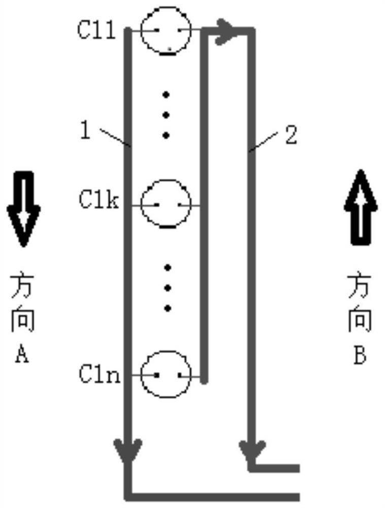
[0040] Such as figure 1 As shown, the current sharing circuit structure of the present invention is a single group of a large number of capacitors connected in parallel, including several capacitors C11, ..., C1k, ..., C1n, positive group connection row 1 and negative group connection row 2, Several capacitors C11,..., C1k,..., C1n are connected in parallel, the positive poles of all the above capacitors are connected to the positive group connecting row 1, and the positive group connecting row 1 is connected to the positive electrodes of all capacitors Then go out along the capacitor arrangement direction A (that is, along the direction from capacitor C11 to C1n);

[0041] The negative poles of all the above capacitors are connected to the negative group connection row 2, and the negative group connection row 2 is connected to the negative electrodes of all capacitors and then goes out along the capacitor arrangement direction B (that is, along the direction of the capacitor...

Embodiment 2

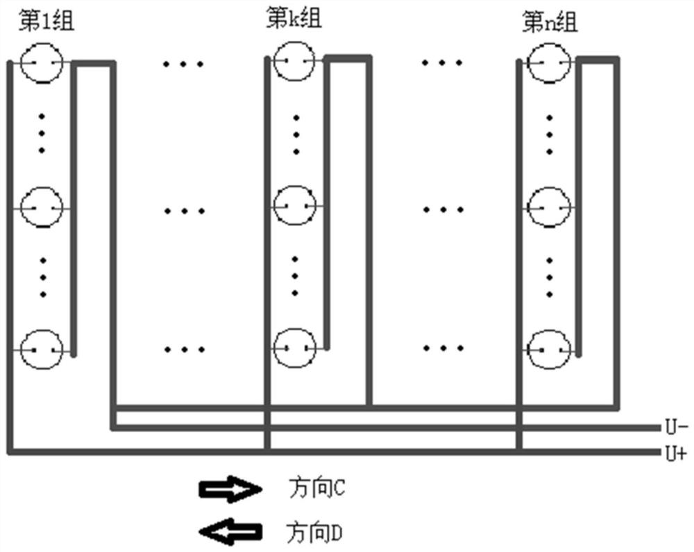
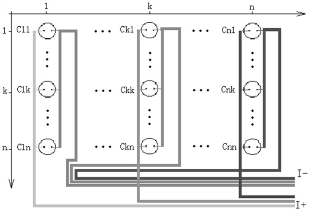
[0048] Such as Figure 1 to Figure 3 As shown, the difference between this embodiment and Embodiment 1 is that this embodiment provides a current sharing circuit structure with multiple groups of large capacitors connected in parallel, including multiple groups of a single group of large capacitors connected in parallel as described in Embodiment 1. A current sharing circuit structure, and multiple groups of a single group of a large number of capacitors connected in parallel to the current sharing circuit structure are arranged side by side to form a capacitor group parallel matrix structure;

[0049] Such as figure 2 As shown, the positive poles of all capacitor groups are aggregated and output U+ along the direction C of all capacitor groups; the negative electrodes of all capacitor groups are aggregated and output along the direction D of all capacitor groups, and the routing direction is rotated 180 degrees to the last capacitor group. In order to output U- along the di...

Embodiment 3

[0054] Such as Figure 1 to Figure 5 As shown, the difference between this embodiment and Embodiment 1 is that this embodiment provides a magnetic field coil power supply for a capacitive energy storage spherical tokamak device, including a plurality of bolt-type electrolytic capacitors, and the plurality of bolt-type electrolytic capacitors Set on the frame body, the frame body includes multiple layers, and multiple capacitors are arranged on each layer according to embodiment 2, and multiple groups of capacitor groups are also arranged between layers according to embodiment 2; and between adjacent capacitors and the frame body Insulation measures are provided between the layers to avoid mutual influence.

[0055] The plurality of bolt-type electrolytic capacitors are arranged and connected according to the current-sharing circuit structure in which a large number of groups of capacitors are connected in parallel as described in Embodiment 3, and the length of the discharge c...


PUM


Abstract

The invention discloses a current sharing circuit structure with a large number of capacitors connected in parallel and a spheromak device power supply. According to the current sharing circuit structure, a single-group capacitor structure comprises a plurality of capacitors, a positive group connecting bar and a negative group connecting bar, the plurality of capacitors are connected in parallel, the positive electrodes of all the capacitors are connected to the positive group connecting bar, the positive group connecting bar is connected with the positive electrodes of all the capacitors and then leads out along a capacitor arrangement direction A, the negative electrodes of all the capacitors are connected to the negative group connecting bar, the negative group connecting bar is connected with the negative electrodes of all the capacitors and then leads out along a capacitor arrangement direction B, the wiring direction is changed to be along the capacitor arrangement direction A by rotating 180 degrees at the position of the last capacitor, the wiring direction and the outgoing line of the positive group connecting bar are gathered and led out to form a loop, and the direction A and the direction B are parallel and opposite; and multiple groups of capacitor structures comprise multiple groups of single-group capacitor structures, and the multiple groups of single-group capacitor structures are arranged side by side to form a capacitor group parallel matrix structure. According to the invention, the capacitor group parallel matrix structure can achieve the current sharing effect without adding extra devices.

Description

technical field [0001] The invention relates to the technical field of current sharing with a large number of capacitors connected in parallel, in particular to a current sharing circuit structure with a large number of capacitors connected in parallel and a power supply for a ball mark device. Background technique [0002] In the prior art, an impedance matching part is connected in series with the capacitor, and the impedance matching part uses a power resistor, a temperature-sensitive resistor with a positive temperature coefficient or an inductive reactance. If this current sharing method is applied to the capacitor current sharing, the disadvantage is that the series impedance It will consume energy in the circuit, and the additional components will increase the cost. [0003] Therefore, in a circuit in which a large number of capacitors are connected in parallel, there are the following disadvantages: the mutual discharge of the capacitors caused by the parallel connec...

Claims


Application Information

Patent Timeline
Patent Type & Authority Applications(China)
IPC IPC(8): H02J1/10H02J15/00H02J7/00
CPCH02J1/10H02J15/00H02J7/0016
Inventor 陈俊宏宣伟民李维斌王英翘姚列英戟洋郑雪韩艾玻邓茂才甘辉张建金庆华钱锋
Owner SOUTHWESTERN INST OF PHYSICS
Learn More