

Parallel resonant converter and power supply
A technology of resonant converter and resonant inductor, which is applied in the direction of instruments, DC power input conversion to DC power output, electrical components, etc., and can solve the problems of uneven current of two-way resonant converters
- Summary
- Abstract
- Description
- Claims
- Application Information
AI Technical Summary
Problems solved by technology
Method used
Image

Examples
example 1
[0040]1. The topological structure of the resonant converter is: two-way asymmetric half-bridge resonant converter topology;
[0041]2. The resonant inductance shared by the two resonant converters, the excitation inductance of the two transformers, and the primary and secondary windings of the two transformers are magnetically integrated into a pair of magnetic cores to form the first transformer T;
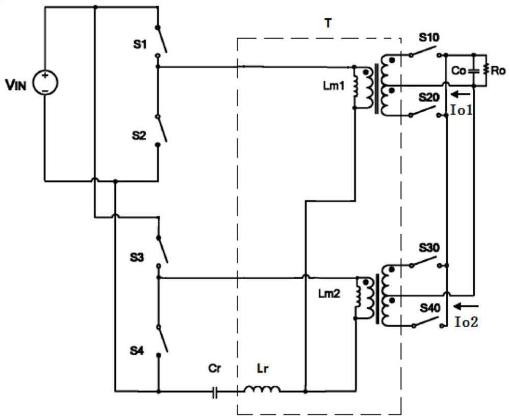
[0042]image 3 It is a schematic diagram of the equivalent circuit of the parallel resonant converter of Example 1 of the embodiment of the present invention, which is the best example of the embodiment of the present invention, such asimage 3 As shown, in Example 1, it is a parallel connection of two asymmetric half-bridge resonant converters, including the first switching devices S1 and S2, the first rectifying devices S10 and S20, and the second switching devices S3, S4, the second rectifier devices S30, S40, the resonant capacitor Cr shared by the two resonant converters, the resonant in...
example 2
[0049]1. The topological structure of the resonant converter is: two-way asymmetric half-bridge resonant converter topology;
[0050]2. The excitation inductance of the two transformers and the primary and secondary windings of the two transformers are magnetically integrated into one pair of magnetic cores to form the first transformer T;
[0051]Figure 4 It is a schematic diagram of the equivalent circuit of the parallel resonant converter of Example 2 of the embodiment of the present invention, such asFigure 4 The parallel resonant converter shown is a parallel connection of two asymmetric half-bridge resonant converters, including the first switching devices S1 and S2, the first rectifying devices S10 and S20, and the second switching devices S3, S4, the second rectifier device S30, S40, the resonant capacitor Cr shared by the two resonant converters and the resonant inductor Lr shared by the two resonant converters, the excitation inductances Lm1, Lm2 of the two transformers and the ...
example 3
[0053]1. The topological structure of the resonant converter is: two-way asymmetric half-bridge resonant converter topology;
[0054]2. The excitation inductance of the two transformers and the primary and secondary windings of the two transformers are magnetically integrated into one pair of magnetic cores to form the first transformer T;
[0055]3. The resonance inductance is the leakage inductance of the transformer T.
[0056]Figure 5 It is a schematic diagram of the equivalent circuit of the parallel resonant converter of Example 3 of the embodiment of the present invention, such asFigure 5 The parallel resonant converter shown is a parallel connection of two asymmetric half-bridge resonant converters, including the first switching devices S1 and S2, the first rectifying devices S10 and S20, and the second switching devices S3, S4, the second rectifier device S30, S40, the resonant capacitor Cr shared by the two resonant converters, the excitation inductances Lm1, Lm2 of the two transfo...
PUM
 Abstract
Description
Claims
Application Information