Buffer starting type permanent magnet coupling direct drive device

A permanent magnet coupling, permanent magnet technology, applied in the direction of permanent magnet clutch/brake, electromechanical device, electric brake/clutch, etc., can solve the problem of additional electronic components, etc., to achieve the effect of small starting current

Pending Publication Date: 2021-07-23
SHANGHAI ORIENTAL MARITIME ENG TECH CO LTD
View PDF0 Cites 0 Cited by
  • Summary
  • Abstract
  • Description
  • Claims
  • Application Information

AI Technical Summary

Problems solved by technology

[0005] The purpose of the present invention is to provide a buffer start type permanent magnet coupling direct drive device to solve the problem in the prior art that the buffer start of the asynchronous start permanent magnet synchronous motor requires additional electronic components

Method used


Image

  • Buffer starting type permanent magnet coupling direct drive device
  • Buffer starting type permanent magnet coupling direct drive device
  • Buffer starting type permanent magnet coupling direct drive device

Examples


Embodiment 1

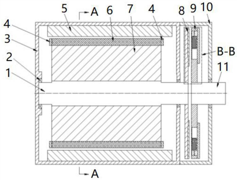
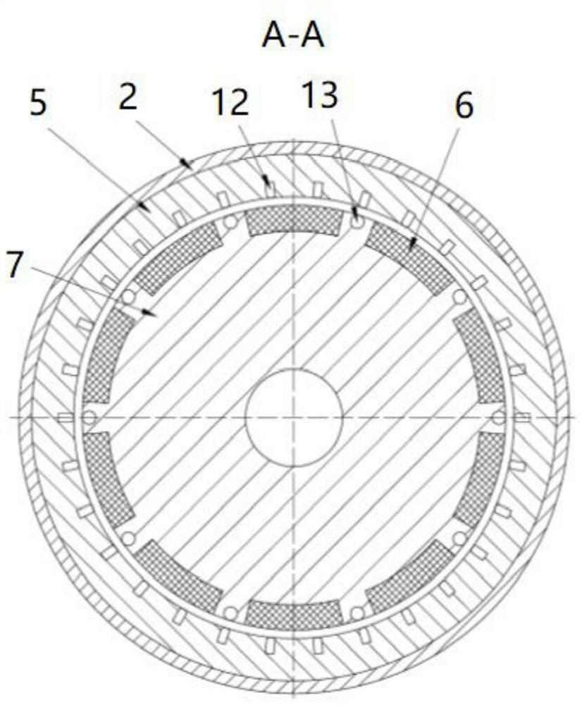
[0040] see Figure 1 to Figure 3 , this embodiment provides a buffer start type permanent magnet coupling direct drive device, including a casing, and a stator assembly, a rotor assembly, a conductor disk assembly 8, a permanent disk assembly 9, a main shaft 1 and an output shaft 11 arranged in the casing . The main shaft 1 and the output shaft 11 are respectively rotatably connected to the casing, and the main shaft 1 and the output shaft 11 are arranged concentrically with a gap between them.

[0041] The rotor assembly and the conductor disk assembly 8 are sheathed and fixedly connected to the main shaft 1 respectively, and the conductor disk assembly 8 is arranged on the side of the rotor assembly close to the output shaft 11 . The stator assembly is sleeved on the rotor assembly, and the stator assembly is fixedly connected to the casing. The permanent disk assembly 9 is sheathed and fixedly connected to the output shaft 11 .

[0042] The stator assembly receives exter...

Embodiment 2

[0053] see Figure 1 to Figure 3 , this embodiment provides a buffer start type permanent magnet coupling direct drive device, which is based on the first embodiment of the permanent magnetic disk assembly 9 of the optimal improvement.

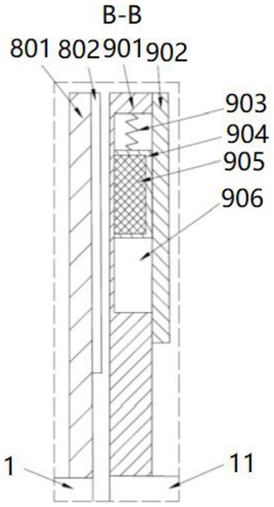
[0054] In this embodiment, the permanent magnetic disk assembly 9 includes a permanent magnetic disk back iron 902 , several second permanent magnets 905 , a fixing frame 901 and an elastic member. The fixing frame 901 is sheathed and fixed on the output shaft 11 , and the permanent magnet back iron is fixed on the side of the fixing frame 901 away from the main shaft 1 .

[0055] The fixing frame 901 is provided with a plurality of accommodation grooves facing the side of the permanent magnet back iron, and the plurality of accommodation grooves are respectively matched with the permanent magnet back iron to form a plurality of slideways 906, and a plurality of second permanent magnets 905 are radially slidably connected to the plurality of s...


PUM


Abstract

The invention discloses a buffer starting type permanent magnet coupling direct drive device which comprises a machine shell and a stator assembly, a rotor assembly, a conductor disc assembly, a permanent magnet disc assembly, a main shaft and an output shaft which are set in the machine shell; the main shaft and the output shaft are rotationally connected with the machine shell and are concentrically arranged, and a gap is formed between the main shaft and the output shaft. The rotor assembly and the conductor disc assembly respectively sleeve and are fixedly connected to the main shaft. The conductor disc assembly is arranged on one side, close to the output shaft, of the rotor assembly. The stator assembly is sleeved on the rotor assembly, and the stator assembly is fixedly connected to the machine shell. The permanent magnet disc assembly sleeves and is fixedly connected to the output shaft. External multi-phase alternating current is introduced into the stator assembly to generate a rotating magnetic field, the rotating magnetic field interacts with a first permanent magnetic field generated by the rotor assembly, and the rotor assembly is driven to rotate to drive the main shaft and the conductor disc assembly to rotate. The conductor disc assembly cuts a second permanent magnetic field on the permanent magnetic disc assembly so as to induce and generate torque to drive the permanent magnetic disc assembly and the output shaft to rotate.

Description

technical field [0001] The invention belongs to the technical field of permanent magnet drives, in particular to a buffer start type permanent magnet coupling direct drive device. Background technique [0002] The permanent magnet synchronous motor adopts permanent magnet excitation, which has the advantages of high power factor, high efficiency, and a wide range of high-efficiency operation. It can also be designed to directly drive the load with a high number of poles and shorten the transmission chain. For asynchronously started permanent magnet synchronous motors, during the starting process, the starting cage on the permanent magnet rotor cuts the rotating magnetic field generated after the stator winding is energized, thereby generating an induced current on the starting cage, which in turn generates torque to drive the permanent magnet rotor to run. [0003] When the asynchronous start permanent magnet synchronous motor drives a load with a large moment of inertia, it...

Claims


Application Information

Patent Timeline
Patent Type & Authority Applications(China)
IPC IPC(8): H02K21/46H02K21/14H02K1/27H02K7/10H02K49/10H02K5/04
CPCH02K1/274H02K5/04H02K7/10H02K21/14H02K21/46H02K49/102H02K49/108H02K2201/12
Inventor 吴明马玉顺范欣马银飞何超江雯璟
Owner SHANGHAI ORIENTAL MARITIME ENG TECH CO LTD
Why Eureka
Try Eureka