Roll forming metal plate automatic feeding equipment for fan shell manufacturing
A rolling forming and automatic feeding technology, which is applied in metal processing equipment, manufacturing tools, feeding devices, etc., can solve problems such as the limitation of feeding range, and achieve the effect of improving efficiency and expanding range
- Summary
- Abstract
- Description
- Claims
- Application Information
AI Technical Summary
Problems solved by technology
Method used
Image

Examples
Embodiment 1
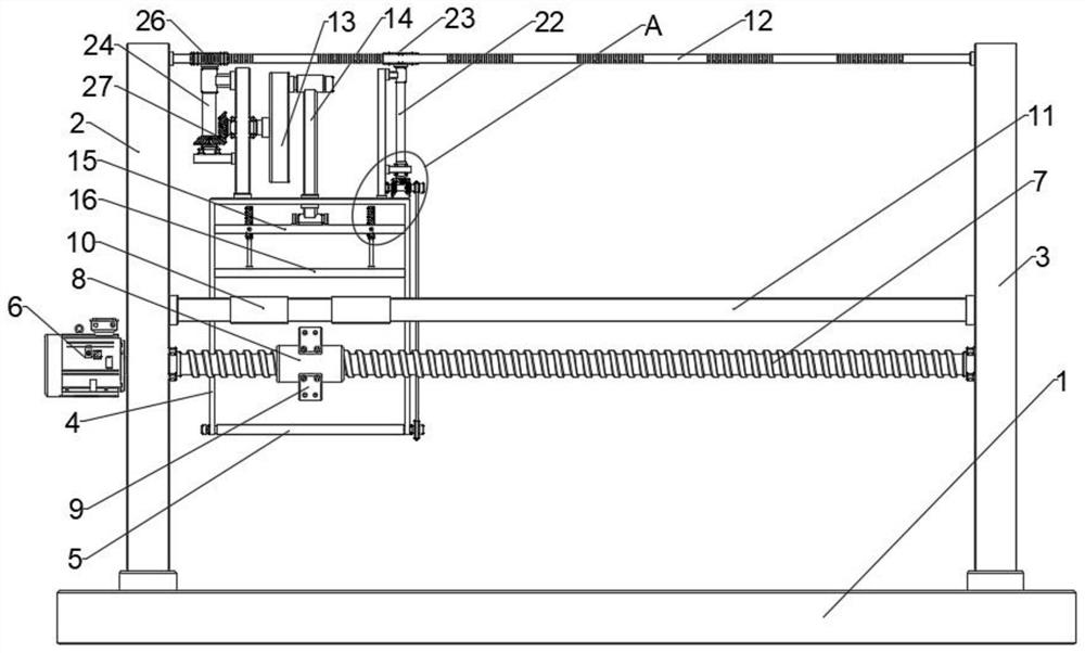
[0033] see figure 1 , a rolling forming sheet metal automatic feeding equipment for fan casing manufacturing, the rolling forming sheet metal automatic feeding equipment for fan casing manufacturing includes a base 1 for installing a fan casing manufacturing workbench, fixed on the base 1 The first vertical board 2 and the second vertical board 3 and the box body 4 used for containing materials are movably arranged on the top of the base 1, and the lower part of the box body 4 is provided with an openable and closed opening and closing plate 5, A drive mechanism for driving the box body 4 to move horizontally is installed between the first riser 2 and the second riser 3;
[0034] The box body 4 is also equipped with a power mechanism for driving the opening and closing plate 5 to turn over. When the drive mechanism works, it will drive the box body 4 to move horizontally, so that the feeding position of the box body 4 is changed, and Simultaneously, the power mechanism trigge...
Embodiment 2
[0038] see figure 1 , the drive mechanism includes an output assembly installed between the first riser 2 and the second riser 3 for driving the horizontal movement of the box body 4 and an output assembly arranged between the first riser 2 and the second riser 3 Between the second risers 3 and connected with the box body 4 is a sliding fitting structure for guiding the movement of the box body 4 .
[0039] In the embodiment of the present invention, when the output assembly is working in the forward direction, the drive box 4 moves horizontally toward the second riser 3, and during this process, the sliding fitting structure guides the box 4 to ensure the movement of the box 4 On the contrary, the drive box 4 moves toward the first vertical plate 2 to the initial position, which is convenient for the next feeding.
Embodiment 3
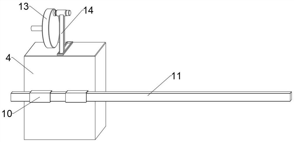
[0041] see figure 1, the output assembly includes an output device 6 mounted on the side of the first riser 2, rotatably installed between the first riser 2 and the second riser 3 and connected to the output device 6 The screw rod 7 and the casing 8 sleeved on the screw rod 7 for driving the movement of the box body 4;
[0042] The casing 8 is fixedly connected to the box body 4 through two connecting plates 9 , and the inner wall thereof is provided with threads that cooperate with the screw rod 7 .
[0043] It should be noted that the above-mentioned output device 6 is a servo motor whose output end can be driven bidirectionally, which is convenient to drive the screw rod 7 to rotate forward or reversely, so that the box body 4 can move bidirectionally.
[0044] In the embodiment of the present invention, when the output device 6 is working in the forward direction, the driving screw 7 is rotated in the forward direction, and the casing 8 is threadedly matched with the scre...
PUM
 Abstract
Description
Claims
Application Information
 - R&D
- Intellectual Property
- Life Sciences
- Materials
- Tech Scout
- Unparalleled Data Quality
- Higher Quality Content
- 60% Fewer Hallucinations
Browse by: Latest US Patents, China's latest patents, Technical Efficacy Thesaurus, Application Domain, Technology Topic, Popular Technical Reports.
© 2025 PatSnap. All rights reserved.Legal|Privacy policy|Modern Slavery Act Transparency Statement|Sitemap|About US| Contact US: help@patsnap.com