
Injection molding machine convenient to demold and capable of preventing adhesion

An anti-adhesion and injection molding machine technology, applied in the field of injection molding machines, can solve problems such as damage to injection molding machines and injection molding products, and that the injection molding machine cannot be quickly demolded, so as to facilitate the demoulding work and speed up the demoulding efficiency.

Inactive Publication Date: 2021-07-27
杜小虎
View PDF0 Cites 0 Cited by
  • Summary
  • Abstract
  • Description
  • Claims
  • Application Information

AI Technical Summary

Problems solved by technology

[0004] Based on the technical problem that the existing injection molding machine cannot be demoulded quickly after the injection molding work is completed, and at the same time, the injection molding machine and the injection molded product are easily damaged to varying degrees during demoulding. machine

Method used


Image

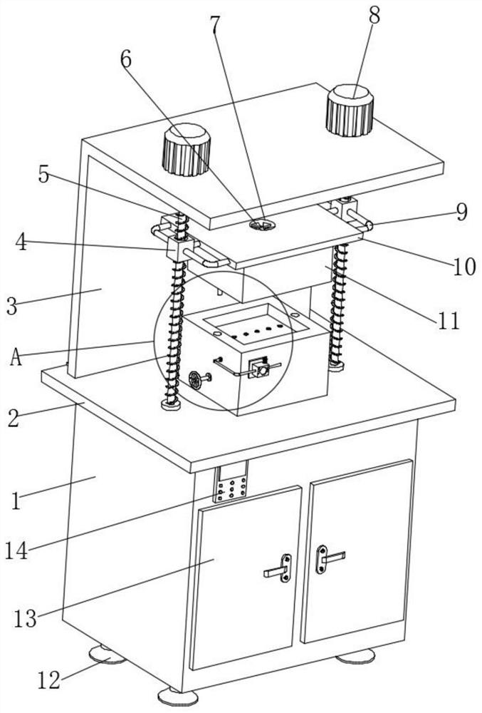
  • Injection molding machine convenient to demold and capable of preventing adhesion
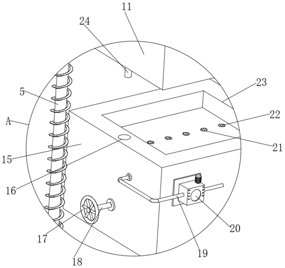
  • Injection molding machine convenient to demold and capable of preventing adhesion
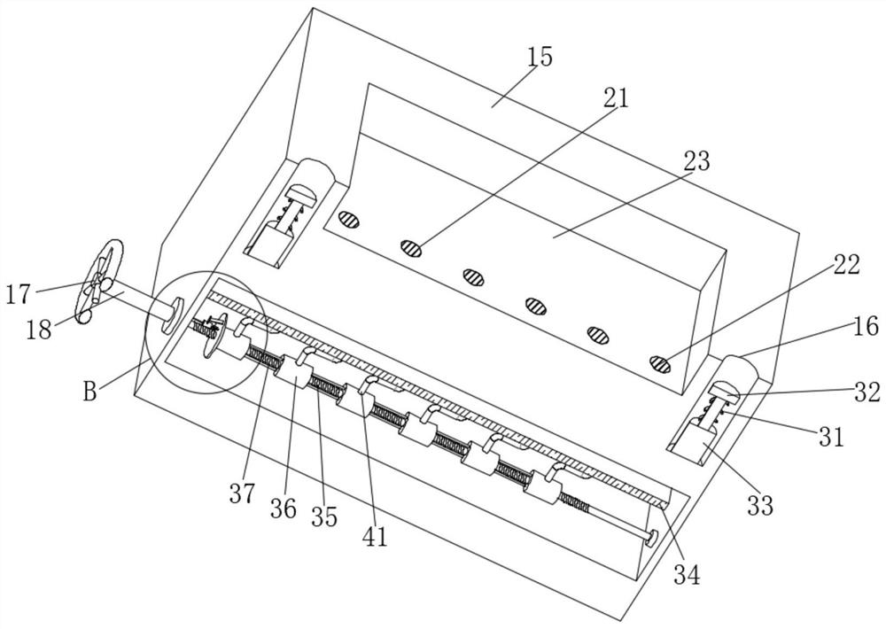
  • Injection molding machine convenient to demold and capable of preventing adhesion

Examples


Embodiment 1

[0031] refer to Figure 1-6 , an injection molding machine for easy demoulding and anti-adhesion, comprising a table body 1, a base 12, a box door 13 and a control panel 14, the top of the table body 1 is fixedly connected with a top plate 2, and the top of the top plate 2 is fixedly connected with a baffle plate 3, The top of the baffle plate 3 is fixedly connected with a motor 8, and one end of the output shaft of the motor 8 is fixedly connected with a first threaded screw rod 5, and the peripheral outer wall of the first threaded screw rod 5 is sleeved with a first threaded sleeve 4, and the first threaded sleeve Both sides of the cylinder 4 are fixedly connected with a fixing frame 9, and one end of the fixing frame 9 away from the first threaded sleeve 4 is fixedly connected with a mounting plate 10, and the bottom of the mounting plate 10 is fixedly connected with an upper mold body 11, and the top of the table body 1 is set There is a lower mold body 15, and one side o...

Embodiment 2

[0035] refer to Figure 7 Compared with Embodiment 1, this example also includes a deflector 30 fixedly connected to the outer wall of the heating column 27. The cross section of the deflector 30 is fan-shaped. Since the cross section of the deflector 30 is fan-shaped, when the injection molding material When it falls into the top of the deflector 30, it can drive the heating column 27 to rotate rapidly. During the rotation of the heating column 27, it can drive the steel needle 29 to evenly defoam the injection molding material.


PUM


Abstract

The invention belongs to the technical field of injection molding machines, and particularly relates to an injection molding machine convenient to demold and capable of preventing adhesion. The following scheme is provided aiming at the problems that an existing injection molding machine cannot be quickly demolded after injection molding work is completed, and meanwhile, the injection molding machine and an injection molding product are prone to being damaged to different degrees during demolding. The injection molding machine comprises a table body, a base, a box door and a control panel, wherein the top of the table body is fixedly connected with a top plate, the top of the top plate is fixedly connected with a baffle, the top of the baffle is fixedly connected with a motor, one end of an output shaft of the motor is fixedly connected with a first threaded screw rod, the circumferential outer wall of the first threaded screw rod is sleeved with a first threaded sleeve, and the two sides of the first threaded sleeve are fixedly connected with fixing frames. According to the injection molding machine, an ejection assembly is arranged, so that the demolding work of people is facilitated, and meanwhile, the situation that the injection molding product is adhered to the inner wall of an injection molding groove due to the fact that the demolding work is not successfully carried out for a long time is avoided.

Description

technical field [0001] The invention relates to the technical field of injection molding machines, in particular to an injection molding machine which is convenient for demoulding and anti-adhesion. Background technique [0002] Injection molding machine is also known as injection molding machine or injection machine. It is the main molding equipment for making thermoplastics or thermosetting plastics into various shapes of plastic products using plastic molding molds. Divided into vertical, horizontal, all-electric. The injection molding machine heats the plastic, applies high pressure to the molten plastic, and makes it shoot out to fill the mold cavity. [0003] At present, the injection molding machines on the market still have certain defects in the use process: 1. The existing injection molding machines cannot quickly demould after the injection molding work is completed; 2. The stability is poor during the demoulding process; 3. It is easy to cause Injection moldin...

Claims


Application Information

Patent Timeline
IPC IPC(8): B29C45/03B29C45/26B29C45/40B29C45/43B29C45/74
CPCB29C45/03B29C45/2606B29C45/4005B29C45/43B29C45/74B29C2045/4036
Inventor 杜小虎
Owner 杜小虎
Learn More