Nozzle block, air spinning device and air spinning machine

A technology of air spinning and nozzle block, which can be used in spinning machine, continuous winding spinning machine, textile and paper making, etc., can solve the problems of increasing pressure loss and difficulty in making nozzles.

Pending Publication Date: 2021-07-27
MURATA MASCH LTD
View PDF10 Cites 0 Cited by
  • Summary
  • Abstract
  • Description
  • Claims
  • Application Information

AI Technical Summary

Problems solved by technology

[0005] In the structure of Patent Document 1, since the nozzle is formed in the shape of a Laval nozzle, fabrication of the nozzle is difficult
In the structure of Patent Document 2, there is a step in the middle of the axial direction of the nozzle, and the pressure loss of the air passing through the nozzle becomes large.

Method used


Image

  • Nozzle block, air spinning device and air spinning machine
  • Nozzle block, air spinning device and air spinning machine
  • Nozzle block, air spinning device and air spinning machine

Examples


Embodiment Construction

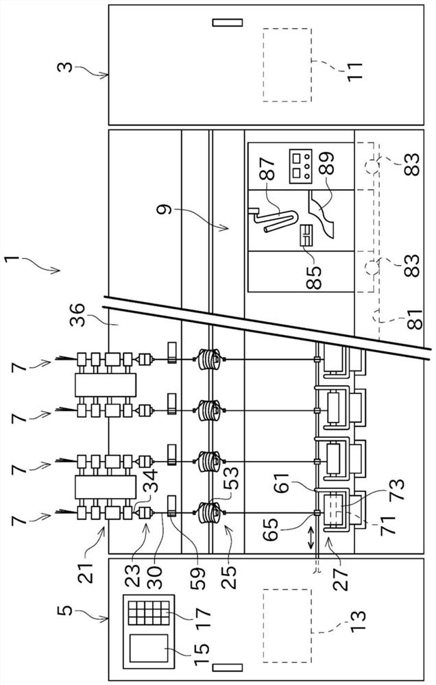
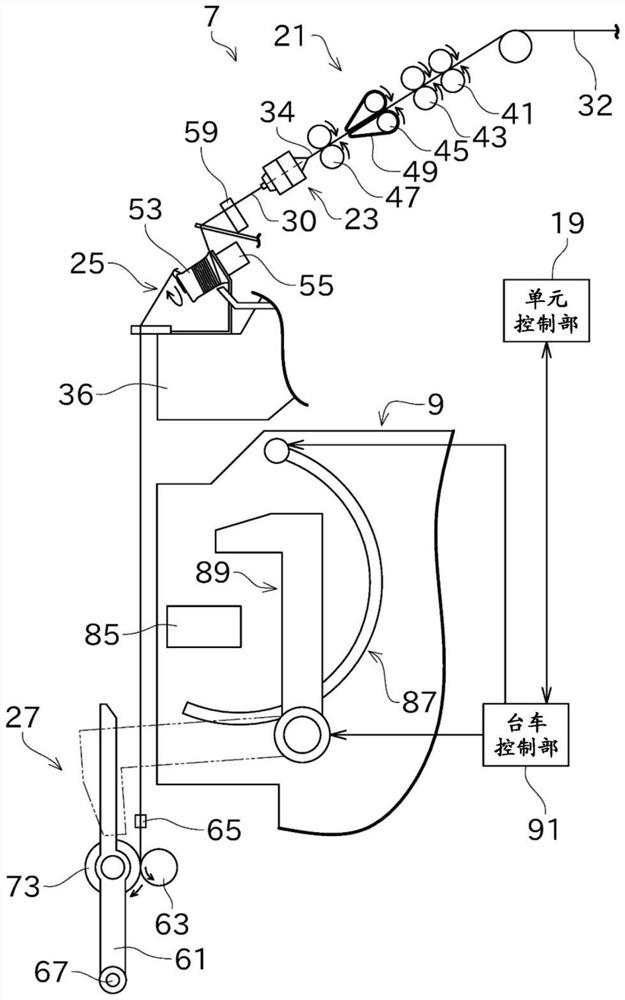
[0036] Next, refer to figure 1 and figure 2 The air spinning machine 1 including the air spinning device 23 including the nozzle block 101 according to the first embodiment of the present invention will be described.

[0037] Such as figure 1 As shown, the air spinning machine 1 includes a blower box 3 , a prime mover box 5 , a plurality of spinning units 7 , and a yarn joining cart 9 . The plurality of spinning units 7 are arranged side by side in a predetermined direction.

[0038] A blower 11 and the like functioning as a negative pressure source are arranged in the blower case 3 .

[0039] A drive source (not shown), a central control unit 13 , a display unit 15 , and an operation unit 17 are arranged in the prime mover case 5 . The driving source provided in the prime mover case 5 includes a motor commonly used by the plurality of spinning units 7 .

[0040] The central control device 13 centrally manages and controls each part of the air spinning machine 1 . Such ...


PUM

PropertyMeasurementUnit
lengthaaaaaaaaaa
angleaaaaaaaaaa
lengthaaaaaaaaaa

Abstract

The invention provides a nozzle block, an air spinning device and an air spinning machine. The nozzle block includes a body portion (111) having a swirl chamber (117) and a spinning nozzle (123). A spinning nozzle (123) includes a straight portion (151) and a section changing portion (153). The straight portion (151) has an ejection port (125) which is located at one end of the nozzle in the axial direction and faces the swirl chamber (117), and extends in an axial direction of the spinning nozzle (123). The section changing portion (153) is connected to the straight portion (151) on the side opposite to the ejection port (125) in the axial direction of the spinning nozzle (123). The diameter of the section changing portion (153) increases from a connecting portion (155) between the straight portion (151) and the section changing portion (153) toward the other end in the axial direction of the spinning nozzle (123). A length (L2) of the straight portion (151) in an axial direction of the spinning nozzle (123) is equal to or larger than 0.4 and equal to or smaller than 4. The opening angle (theta) of the section changing portion (153) is above 5 degrees and below 90 degree.

Description

technical field [0001] The invention relates to a nozzle block, an air spinning device and an air spinning machine. Background technique [0002] Conventionally, there is known a nozzle block that is applied to an air spinning device that applies a swirling airflow to a fiber bundle to generate a yarn in an air spinning machine. Patent Document 1 and Patent Document 2 disclose such a nozzle block. [0003] In the structure of Japanese Patent Application Laid-Open No. 6-10372 (Patent Document 1), the spinning device is composed of a nozzle block, a guide member support, and a rotating spindle. In this spinning device, the portion of the nozzle block that covers the vicinity of the entrance of the hollow guide shaft serves as a hollow chamber. Nozzles are formed on the nozzle block. After the compressed air flows into the air storage part, the compressed air is ejected from the nozzle into the hollow chamber, thereby generating a high-speed swirling airflow near the entranc...

Claims


Application Information

Patent Timeline
Patent Type & Authority Applications(China)
IPC IPC(8): D01H1/115
CPCD01H1/115
Inventor 庄田裕一
Owner MURATA MASCH LTD
Why Eureka
Try Eureka