Anti-deviation ground pile driving device for building engineering construction
A construction engineering and anti-deflection technology, which is applied in construction, foundation structure engineering, sheet pile walls, etc., can solve problems such as the driving efficiency of piles that are prone to deviation, and achieve the effect of improving piling efficiency
- Summary
- Abstract
- Description
- Claims
- Application Information
AI Technical Summary
Problems solved by technology
Method used
Image
Examples
Embodiment 1
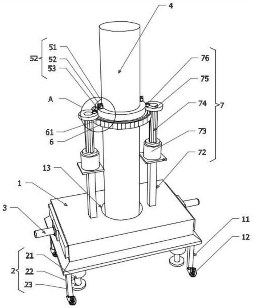
[0039] as attached figure 1Shown: an anti-deflection type ground pile device for construction engineering, including a base 1, the four corners of the bottom end of the base 1 are vertically fixedly installed with a support mechanism 2, and the inside of the base 1 is fixedly installed with Two anti-deflection mechanisms 3, the middle part of the base 1 is inserted with a pile rod 4, the outer wall of the pile rod 4 is detachably installed with two installation mechanisms 5, and the outer ring walls of the two installation mechanisms 5 are fixedly fitted with half The gear ring 6 and the top of the base 1 are fixed vertically with two driving mechanisms 7 arranged side by side.
[0040] as attached figure 2 As shown: among them, the four corners of the bottom end of the base 1 are vertically fixedly connected with supporting columns 11, the specifications of the four supporting columns 11 are consistent and are distributed in a rectangular array with each other, and the bott...
Embodiment 2
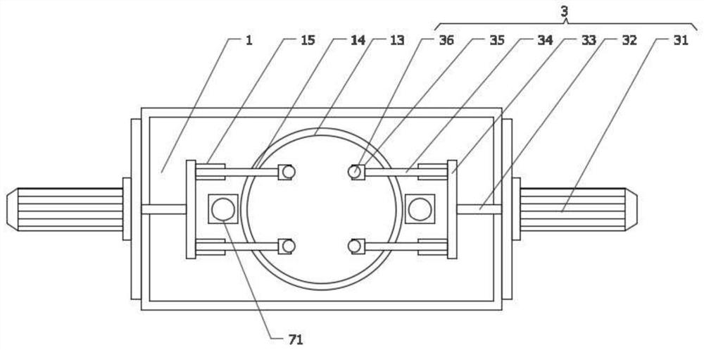
[0043] as attached figure 2 Shown:
[0044] First of all, considering that the specifications of the anti-deflection circular holes 13 are fixed, it is difficult to carry out effective anti-deflection treatment for piles 4 with different outer diameter specifications, so the two anti-deflection mechanisms 3 include the second cylinder 31, The two second air cylinders 31 are vertically and fixedly installed at the center of both ends of the base 1 respectively, and the output ends of the two second air cylinders 31 are fixedly connected with the second shaft 32, and the two second shafts 32 extend through the outer wall of the base 1 respectively. into the inner cavity of the base 1, and are vertically fixedly connected with connecting vertical rods 33, and the opposite sides of the two connecting vertical rods 33 are vertically fixedly connected with two connecting horizontal rods 34, and the four connecting horizontal rods 34 are far away from the corresponding connecting ro...
Embodiment 3
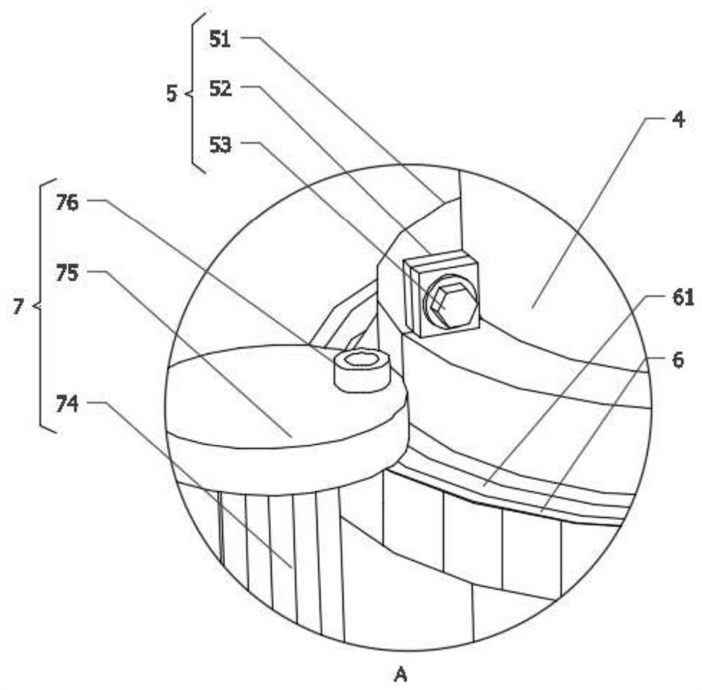
[0047] as attached figure 1 And attached image 3 Shown:
[0048] First of all, considering that the surface of the pile shaft 4 is smooth, it is difficult to cooperate with the rotating shaft 74 in the drive mechanism 7 to realize rotary drilling, so the two mounting mechanisms 5 all include a semi-fixed ring 51, and the two semi-fixed rings 51 are all looped on the pile shaft. 4, the tops of the two ends of the two semi-fixed rings 51 are vertically fixed with mounting pieces 52, and the four mounting pieces 52 are designed to fit side by side. The second screw 53 is installed, and the two half-gear rings 6 are respectively fixedly set on the outer ring wall of the corresponding half-fixed ring 51, and are temporarily set on the outer pole wall of the pile rod 4 through the two half-fixed rings 51, matching the half-gear ring 6 It is convenient to mesh and rotate with the rotating shaft 74 to realize the rotary piling operation of the pile bar 4. The top surfaces of the tw...
PUM
 Abstract
Description
Claims
Application Information
 - R&D
- Intellectual Property
- Life Sciences
- Materials
- Tech Scout
- Unparalleled Data Quality
- Higher Quality Content
- 60% Fewer Hallucinations
Browse by: Latest US Patents, China's latest patents, Technical Efficacy Thesaurus, Application Domain, Technology Topic, Popular Technical Reports.
© 2025 PatSnap. All rights reserved.Legal|Privacy policy|Modern Slavery Act Transparency Statement|Sitemap|About US| Contact US: help@patsnap.com


