Microscope lens magnification switching device
A switching device and microscope technology, applied in the field of microscopes, can solve the problems of inconvenient adjustment of microscope lens switching precision and constant distance adjustment, and achieve the effects of improving the adaptability of observation points, improving stability, and improving observation effects.
- Summary
- Abstract
- Description
- Claims
- Application Information
AI Technical Summary
Problems solved by technology
Method used
Image
Examples
Embodiment 1
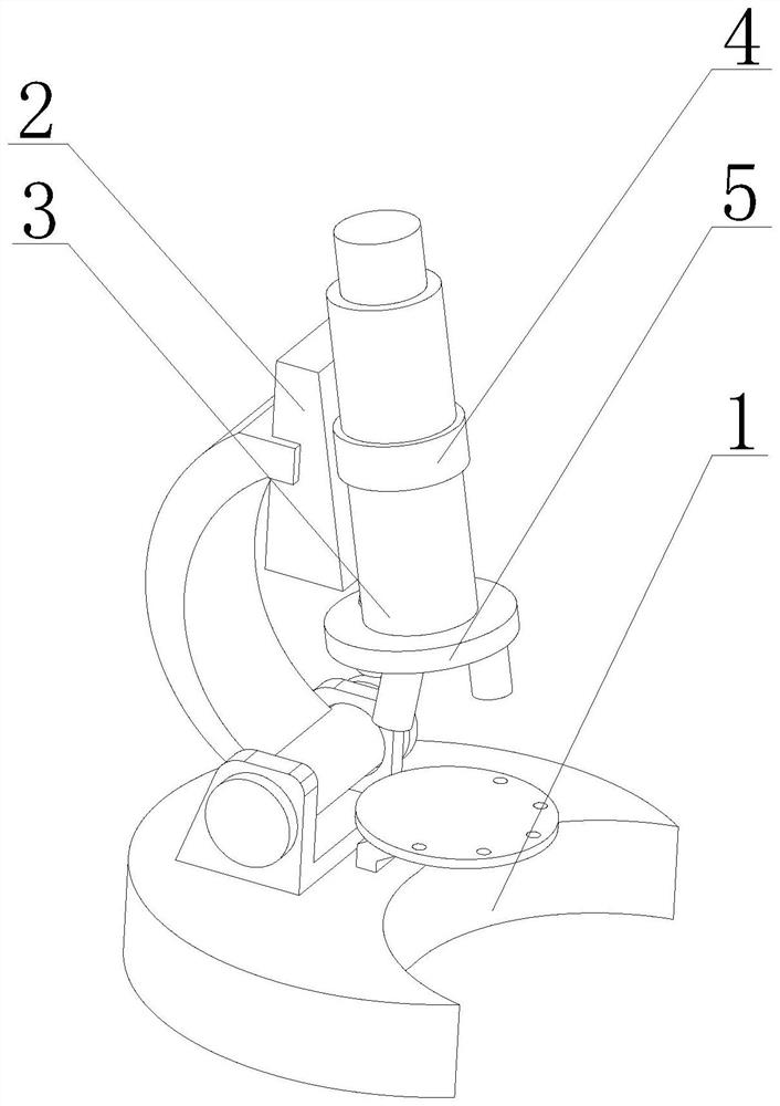
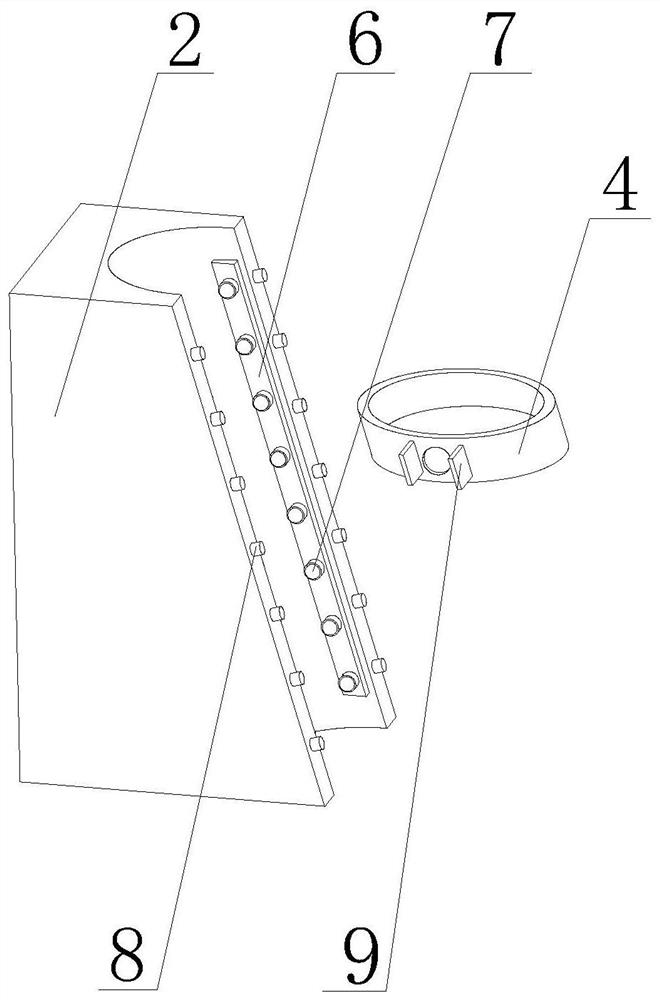
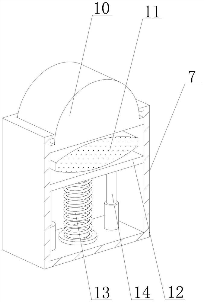
[0031] Such as Figure 1-5 As shown, the present invention provides a microscope lens magnification switching device, comprising a microscope body 1, a support frame 2 and a lens barrel 3, the top of the microscope body 1 is rotationally connected with the bottom of the support frame 2, and the lens barrel 3 is positioned at the bottom of the support frame 2 Set on the right side, the outer wall of the lens barrel 3 is clamped with an adjustment ring 4, the outer wall of the adjustment ring 4 is slidingly connected with the outer wall of the support frame 2, the lens adjustment device 5 is arranged under the bottom of the lens barrel 3, and the outer wall of the support frame 2 is fixed and installed There is a pulley bar 6, and the outer wall of the pulley bar 6 is fixedly equipped with a clamping device 7. In order to adjust the position of the adjusting ring 4, the clamping device 7 can change the distance between the lens barrel 3 and the microscope body 1, so as to adapt t...
Embodiment 2
[0035] Such as Figure 1-5 As shown, on the basis of Embodiment 1, the present invention provides a technical solution: preferably, one side of the elastic member 13 is provided with a support column 14, and the top of the support column 14 is fixedly connected to the bottom of the bearing plate 12, and the support column The outer wall of 14 is embedded with a T-shaped tube 23. When the carrier plate 12 moves down, it will drive the carrier plate 12 to move down, so that the support column 14 enters the inside of the T-shaped tube 23, resulting in a reduction in the internal space of the T-shaped tube 23. Air pressure increases, and the inner wall of T-shaped pipe 23 is slidably connected with movable plate 22, and the top of movable plate 22 is fixedly connected with pop-up piece 8, and the outer wall of pop-up piece 8 is slidably connected with the inner wall of support frame 2, and the outer wall of T-shaped pipe 23 is connected with The inner wall of the support frame 2 i...
Embodiment 3
[0037] Such as Figure 1-5As shown, on the basis of Embodiment 1, the present invention provides a technical solution: preferably, the lens adjusting device 5 is composed of a connecting ring 15, a primary adjusting plate 16 and a secondary adjusting plate 17, and the top of the connecting ring 15 is connected to the mirror The bottom of the tube 3 is fixedly connected, the outer wall of the primary adjustment plate 16 is provided with an embedding hole 19, and the embedding hole 19 is evenly opened on the top of the primary adjustment plate 16, and the primary adjustment plate 16 and the secondary adjustment plate 17 are set. Multiple adjustments are conducive to improving the observation of the position of the object. The bottom of the connecting ring 15 is fixedly equipped with an elastic expansion member 18. The outer wall of the elastic expansion member 18 is embedded and connected with the inner wall of the insertion hole 19. The primary adjustment plate 16 is elastic whe...
PUM
 Abstract
Description
Claims
Application Information
 - R&D
- Intellectual Property
- Life Sciences
- Materials
- Tech Scout
- Unparalleled Data Quality
- Higher Quality Content
- 60% Fewer Hallucinations
Browse by: Latest US Patents, China's latest patents, Technical Efficacy Thesaurus, Application Domain, Technology Topic, Popular Technical Reports.
© 2025 PatSnap. All rights reserved.Legal|Privacy policy|Modern Slavery Act Transparency Statement|Sitemap|About US| Contact US: help@patsnap.com


