Automatic anesthesia system

An anesthetic and driving mechanism technology, applied in the medical field, can solve the problems of increasing the work intensity of medical staff, unfavorable treatment of patients, difficulty in automatic control, etc., and achieve the effect of improving convenience, reducing cumbersome actions, and avoiding tingling sensation

Inactive Publication Date: 2021-07-30
魏素芹
View PDF0 Cites 0 Cited by
  • Summary
  • Abstract
  • Description
  • Claims
  • Application Information

AI Technical Summary

Problems solved by technology

[0003] However, when the current anesthesiology department performs local anesthesia on oral or nasal patients, the commonly used technical means are mostly syringe-type injections of anesthetic agents. At the beginning, there was a certain resistance, which was not conducive to the doctor's treatment of patients. In addition, although some anesthesia departments have adopted painless local anesthesia, manual operations are still required, and it is difficult to automate the entire process. At the same time, anesthesiologists need to use various medical devices in clinical operations. During the treatment of patients, medical staff continue to take and place medical devices from different places, which also causes some inconvenience and increases the work of medical staff. strength

Method used


Image

  • Automatic anesthesia system
  • Automatic anesthesia system
  • Automatic anesthesia system

Examples


Embodiment 1

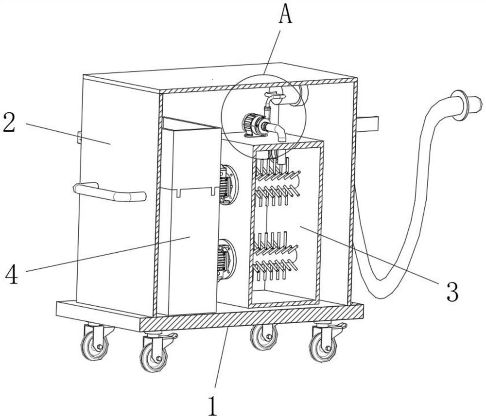
[0049] Such as Figure 1-14 As shown, an automated anesthesia system according to an embodiment of the present invention includes: a driving mechanism 1 , a main body mechanism 2 , a stirring and mixing mechanism 3 and a storage mechanism 4 .

[0050] Wherein, the driving mechanism 1 includes a base plate 11, a first universal wheel 12, a second universal wheel 13, a third universal wheel 14 and a fourth universal wheel 15, and the first universal wheel 12 is installed on the bottom front side of the base plate 11. One end of the second universal wheel 13 is installed on the base plate 11 away from the end of the bottom front side of the first universal wheel 12, and the third universal wheel 14 is installed on the bottom end of the base plate 11 at the rear side of the first universal wheel 12. Four universal wheels 15 are installed on the base plate 11 and are positioned at the bottom end of the second universal wheel 13 rear side;

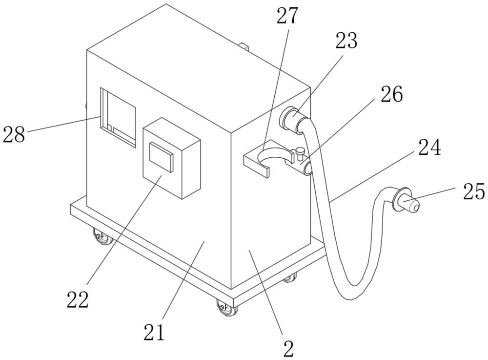
[0051] Wherein, the main mechanism 2 inc...

Embodiment 2

[0071] Such as Figure 6-Figure 8 as well as Figure 12-Figure 14 The difference between the illustrated embodiment and Embodiment 1 is that the storage mechanism 4 includes a support base 41, a medical device storage box 42, and an electric cylinder 43, and the support base 41 is welded to the side of the box body 21 near the anesthetic agent storage box 31. At the bottom of the inner cavity, the medical equipment storage box 42 is installed on the top of the supporting base 41. The electric cylinder 43 is screwed to the rear side of the outer wall of the box body 21 and is located on one side of the medical equipment storage box 42, and the electric cylinder 43 is connected to the medical equipment storage box 42. Correspondingly, the piston rod of the electric cylinder 43 penetrates through the outer wall of the box body 21, and is welded with the outer wall of the medical device storage box 42 facing the side of the electric cylinder 43, and the piston rod of the electric ...

Embodiment 3

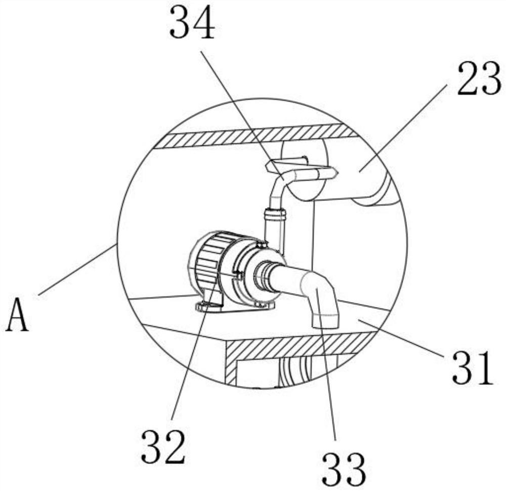
[0075] Such as image 3 , Figure 5 as well as Figure 9 As shown, the difference between this embodiment and Embodiment 2 is that 210 is installed in the inner cavity of the connector 23, and 210 is detachably connected to the connector 23, and the hose 24 is detachably connected to the connector 23. , the atomizing spray head 25 and the hose 24 are detachably connected.

[0076] By adopting the above-mentioned technical scheme, 210 can filter the anesthetic agent in the anesthetic agent storage box 31. After using for a period of time, the medical staff can disassemble and replace the hose 24 and the atomizing nozzle 25 respectively. At the same time, the hose 24 After disassembly, the 210 can be removed and cleaned to avoid its clogging, and it can be reinstalled after the cleaning is completed.


PUM


Abstract

The invention discloses an automatic anesthesia system, which relates to the technical field of medical equipment and comprises a driving mechanism, a main body mechanism, a stirring and uniform mixing mechanism and a storage mechanism. Under the action of the driving mechanism, the automatic anesthesia system can be supported and driven; by holding the atomizing nozzle by hand, the anesthetic in the anesthetic storage box can be accurately sprayed into the oral cavity of a patient, so that local anesthesia is realized after the patient inhales the anesthetic, and the pricking feeling caused by injection to the patient is avoided; under the stirring action of the stirring and uniform mixing mechanism, the anesthetic can be fully and uniformly mixed, so that the clinical medical anesthetic effect can be better achieved; under the control of the PLC, an operation screen of the PLC is operated, and under the action of the PLC, the automatic anesthesia system can automatically stir and extract anesthetics; under the action of the storage mechanism, an anesthetist can conveniently place various medical instruments required by anesthesia, so that the medical instruments are stored totally.

Description

technical field [0001] The invention relates to the field of medical technology, in particular to an automatic anesthesia system. Background technique [0002] It is generally believed that anesthesia is a reversible functional inhibition of the central nervous system and peripheral nervous system produced by drugs or other methods. This inhibition is mainly characterized by loss of sensation, especially pain. The term anesthesia, as the name suggests, means numbness and numbness, and drunk means drunken coma. Therefore, the meaning of anesthesia is to use drugs or other methods to temporarily deprive the patient of the whole or part of the sensation, so as to achieve the purpose of painless surgical treatment. [0003] However, when the current anesthesiology department performs local anesthesia on oral or nasal patients, the commonly used technical means are mostly syringe-type injections of anesthetic agents. At the beginning, there was a certain resistance, which was n...

Claims


Application Information

Patent Timeline
Patent Type & Authority Applications(China)
IPC IPC(8): A61M31/00A61M19/00
CPCA61M19/00A61M31/00A61M2205/3334A61M2205/3365A61M2210/0625
Inventor 魏素芹王园园张涣君
Owner 魏素芹
Why Eureka
Try Eureka