Backwash filtering equipment and backwash filtering method thereof

A technology of backwashing filtration and equipment, which is applied in the field of hydraulic systems and can solve problems such as poor backwashing effect and difficulty in moving the handle

Pending Publication Date: 2021-07-30
SHAANXI RUN TOP TRANSMISSION TECH CORP
View PDF0 Cites 0 Cited by
  • Summary
  • Abstract
  • Description
  • Claims
  • Application Information

AI Technical Summary

Problems solved by technology

[0003] The purpose of the present invention is to provide a kind of backwash filter equipment, which not only solves the problem that the handle of the existing backwash filter device is difficult to move in the high-pressure system, but also solves the poor backwash effect of the existing backwash filter device in the low-pressure system The problem

Method used


Image

  • Backwash filtering equipment and backwash filtering method thereof
  • Backwash filtering equipment and backwash filtering method thereof
  • Backwash filtering equipment and backwash filtering method thereof

Examples


Embodiment Construction

[0025] The present invention will be described in detail below in conjunction with the accompanying drawings and specific embodiments.

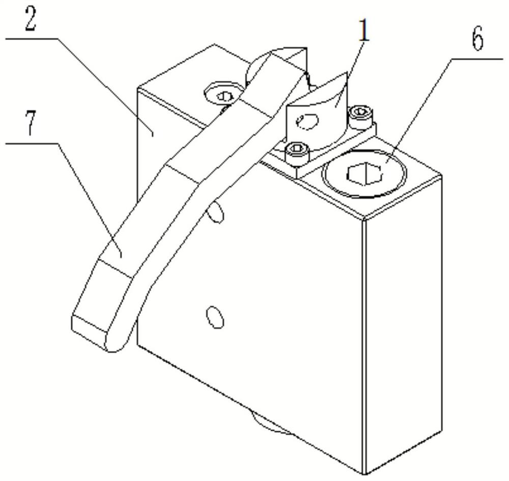
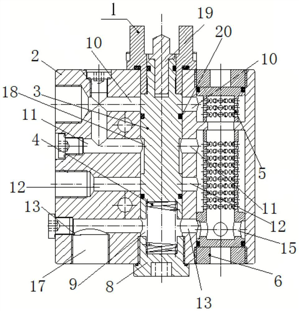
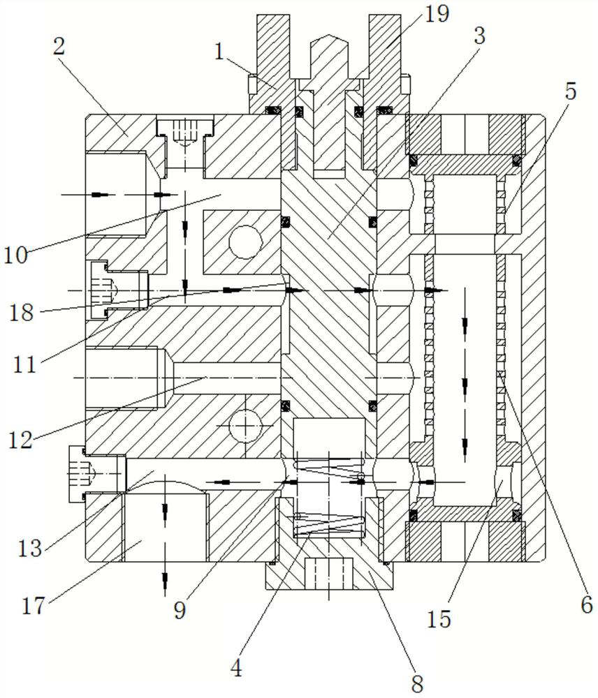
[0026] A kind of backwash filter equipment of the present invention, as figure 1 , 2 As shown, including the valve body 2, the valve body 2 is provided with a valve stem 3 along the vertical direction, the lower end of the valve stem 3 is provided with a compression spring 4, the upper end of the compression spring 4 is engaged with the valve stem 3, and the lower end of the compression spring 4 There is a spring seat 8; there is an oil guide gap 9 between the lower end of the valve stem 3 and the spring seat 8; the valve body 2 is provided with oil port A10, oil port B11, and oil port along the horizontal direction from top to bottom. C12 and oil port D13; one side of the valve body 2 is provided with a filter element A5, and the lower part of the filter element A5 is provided with a filter element B6. One end of the port D13 is connected;...


PUM


Abstract

The invention discloses backwashing filtering equipment which comprises a valve body, a valve rod is arranged in the valve body in the vertical direction, a compression spring is arranged at the lower end of the valve rod, the upper end of the compression spring is clamped with the valve rod, and a spring clamping seat is arranged at the lower end of the compression spring; an oil guide gap is formed between the lower end of the valve rod and the spring clamping seat; an oil port A, an oil port B, an oil port C and an oil port D are sequentially formed in the valve body from top to bottom in the horizontal direction; an oil inlet and a filter element A are further arranged at the two ends of the valve body respectively, a filter element B is arranged below the filter element A, and an oil guide port is formed in the lower end of the filter element B and communicates with one end of the oil port D; and an oil outlet is formed in the bottom of the valve body and communicates with the other end of the oil port D. The invention further discloses a backwash filtering method, the problem that a handle of an existing backwash filtering device is difficult to shift in a high-pressure system is solved, and the problem that an existing backwash device is poor in backwashing effect in a low-pressure system is also solved.

Description

technical field [0001] The invention belongs to the technical field of hydraulic systems, and relates to backwashing and filtering equipment. The invention also relates to the above-mentioned backwashing and filtering method using the above-mentioned equipment. Background technique [0002] The existing backwash filter generally uses a ball valve to complete the work, but in a high-pressure system, it becomes extremely difficult to move the handle of the ball valve, and sometimes it is even necessary to complete the working process of the backwash filter by knocking the handle. However, in a low-pressure system, such as a cooling system, when using a traditional backwash filter, its liquid outlet will still be open, which will cause the working medium to be diverted, greatly reducing the backwash effect. Contents of the invention [0003] The purpose of the present invention is to provide a kind of backwash filter equipment, which not only solves the problem that the handl...

Claims


Application Information

Patent Timeline
Patent Type & Authority Applications(China)
IPC IPC(8): B01D29/68B01D29/50B01D29/11
CPCB01D29/114B01D29/50B01D29/688
Inventor 任发勋柯超田军
Owner SHAANXI RUN TOP TRANSMISSION TECH CORP
Why Eureka
Try Eureka