Mechanical plate milling device
A milling device and plate technology, which is applied to metal processing machinery parts, positioning devices, milling machine equipment, etc., can solve the problems of the service life of the milling device and the inconvenience of heat loss.
- Summary
- Abstract
- Description
- Claims
- Application Information
AI Technical Summary
Problems solved by technology
Method used
Image
Examples
Embodiment 1
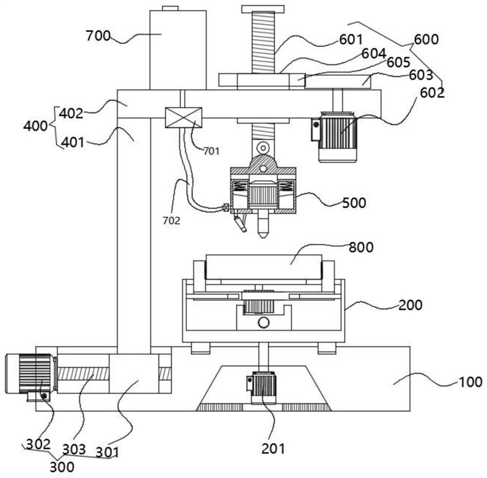
[0058] Such as figure 1 As shown, in an embodiment of the present invention, a mechanical plate milling device includes:
[0059] base 100;
[0060] The clamp body 200 is arranged on the base 100;
[0061] A support frame 400, the horizontal position of the support frame 400 on the base 100 is adjusted by a horizontal adjustment member;
[0062] The processing part 500 is located above the fixture part 200, the height of the processing part 500 in the vertical direction is adjusted by the height adjustment part 600, and the height adjustment part 600 is arranged on the support part 400;
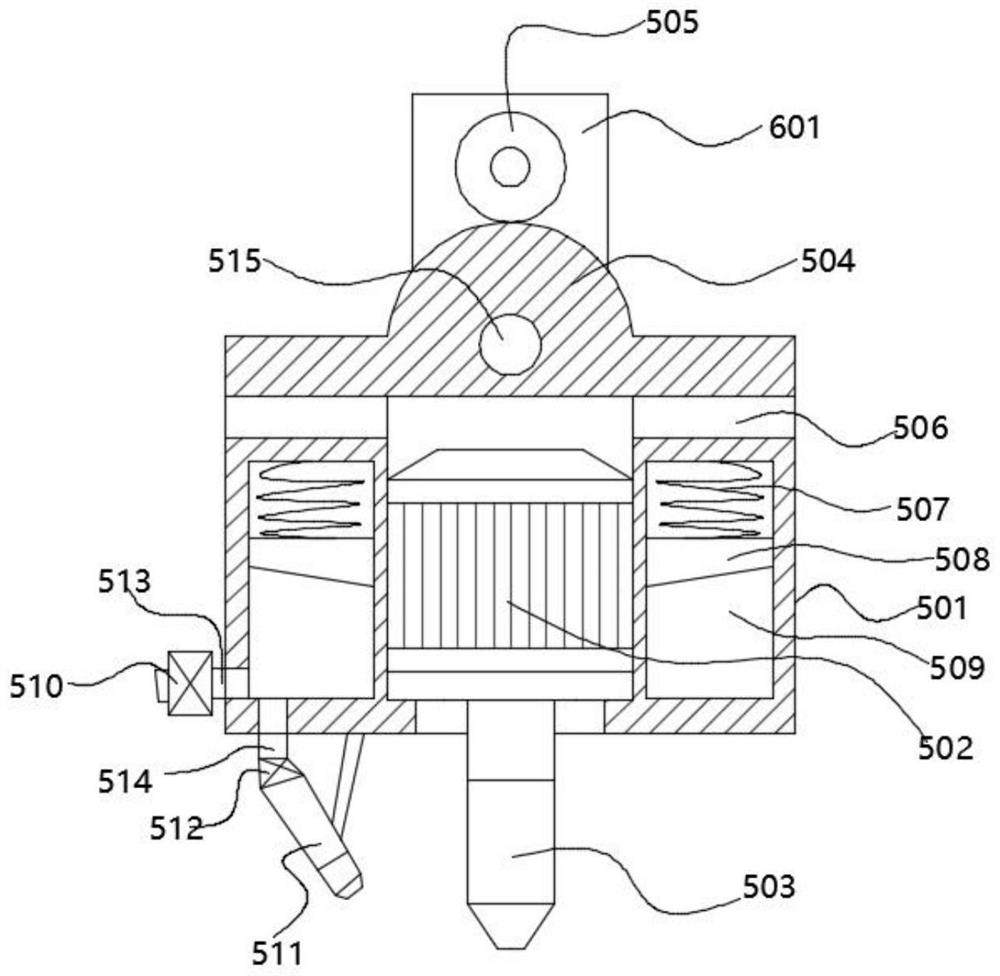
[0063] Further, such as Figure 1-2 As shown, in the preferred embodiment provided by the present invention, the workpiece 500 includes a box body 501, a milling motor 502 is fixedly arranged in the box body 501, and a milling tool 503 is installed on the output shaft of the milling motor 502; A liquid storage chamber 509 surrounding the outer ring of the milling motor 502 is opened in th...
Embodiment 2
[0069] Such as figure 1 As shown, in an embodiment of the present invention, a mechanical plate milling device includes:
[0070] base 100;
[0071] The clamp body 200 is arranged on the base 100;
[0072] A support frame 400, the horizontal position of the support frame 400 on the base 100 is adjusted by a horizontal adjustment member;
[0073] The processing part 500 is located above the fixture part 200, the height of the processing part 500 in the vertical direction is adjusted by the height adjustment part 600, and the height adjustment part 600 is arranged on the support part 400;
[0074] Further, such as Figure 1-2 As shown, in the preferred embodiment provided by the present invention, the workpiece 500 includes a box body 501, a milling motor 502 is fixedly arranged in the box body 501, and a milling tool 503 is installed on the output shaft of the milling motor 502; A liquid storage chamber 509 surrounding the outer ring of the milling motor 502 is opened in th...
Embodiment 3
[0083] Such as figure 1 As shown, in an embodiment of the present invention, a mechanical plate milling device includes:
[0084] base 100;
[0085] The clamp body 200 is arranged on the base 100;
[0086] A support frame 400, the horizontal position of the support frame 400 on the base 100 is adjusted by a horizontal adjustment member;
[0087] The processing part 500 is located above the fixture part 200, the height of the processing part 500 in the vertical direction is adjusted by the height adjustment part 600, and the height adjustment part 600 is arranged on the support part 400;
[0088] Further, such as Figure 1-2 As shown, in the preferred embodiment provided by the present invention, the workpiece 500 includes a box body 501, a milling motor 502 is fixedly arranged in the box body 501, and a milling tool 503 is installed on the output shaft of the milling motor 502; A liquid storage chamber 509 surrounding the outer ring of the milling motor 502 is opened in th...
PUM
 Abstract
Description
Claims
Application Information
 - R&D
- Intellectual Property
- Life Sciences
- Materials
- Tech Scout
- Unparalleled Data Quality
- Higher Quality Content
- 60% Fewer Hallucinations
Browse by: Latest US Patents, China's latest patents, Technical Efficacy Thesaurus, Application Domain, Technology Topic, Popular Technical Reports.
© 2025 PatSnap. All rights reserved.Legal|Privacy policy|Modern Slavery Act Transparency Statement|Sitemap|About US| Contact US: help@patsnap.com


