Sensor tin soldering equipment capable of automatically and accurately positioning optical filter
A technology of precise positioning and optical filters, applied in the field of sensors, can solve the problems of sensor parts being damaged and difficult to change
- Summary
- Abstract
- Description
- Claims
- Application Information
AI Technical Summary
Problems solved by technology
Method used
Image
Examples
Embodiment 1
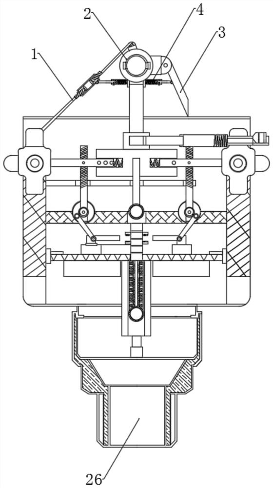
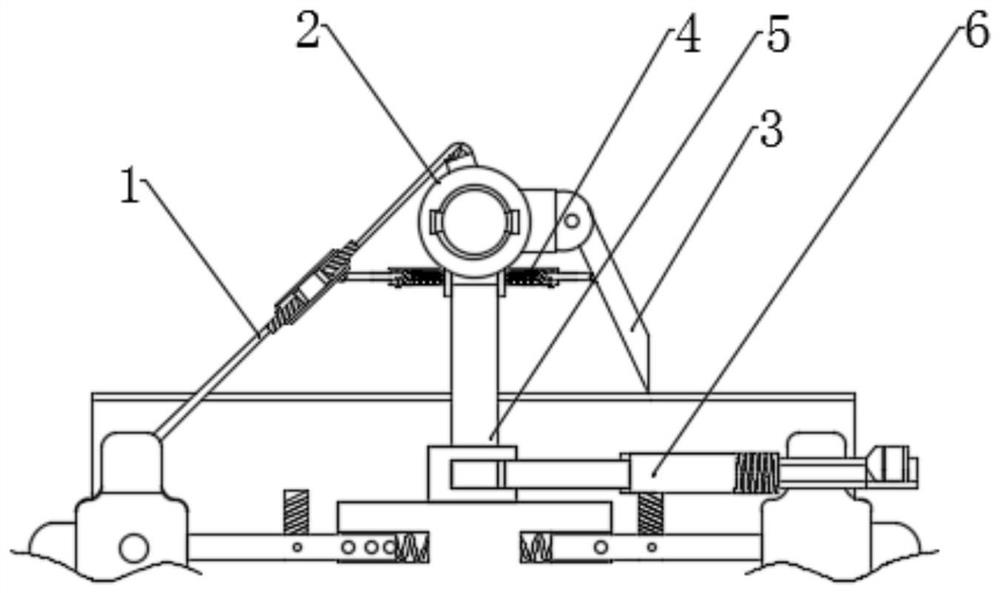
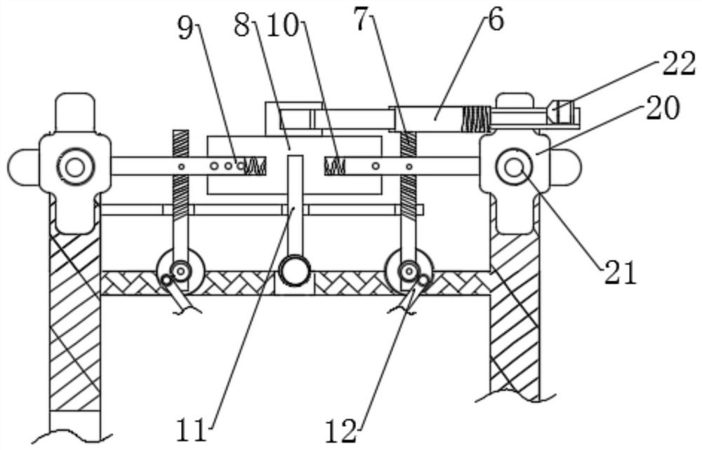
[0027] see Figure 2-Figure 4 , a sensor soldering equipment for automatic and precise positioning of optical filters, comprising a main body 1, a metal frame 2, a solder tube 3 is movably connected to the right end of the metal frame 2, and a pulling member 4 is movably installed between the solder tube 3 and the metal frame 2, and the pulling A support rod 5 is movable installed at the center of the part 4, and the right end of the support rod 5 is sleeved with a fastening seat 6, and the bottom end of the fastening seat 6 is movably connected with a central rod 7, and the middle of the central rod 7 is fixedly connected to the filter at the bottom of the support rod 5. The left and right sides of the optical sheet 8 and the optical filter 8 and the lower end of the fastening seat 6 are movably connected with an active rod 9 .
[0028] Further, the pulling member 4 includes a buffer spring 10, the bottom end of the optical filter 8 is fixedly installed with a strut 11 in the...
Embodiment 2
[0032] see Figure 4 , a sensor soldering equipment for automatic and precise positioning of optical filters, comprising a main body 1, a metal frame 2, a solder tube 3 is movably connected to the right end of the metal frame 2, and a pulling member 4 is movably installed between the solder tube 3 and the metal frame 2, and the pulling A support rod 5 is movable installed at the center of the part 4, and the right end of the support rod 5 is sleeved with a fastening seat 6, and the bottom end of the fastening seat 6 is movably connected with a central rod 7, and the middle of the central rod 7 is fixedly connected to the filter at the bottom of the support rod 5. The left and right sides of the optical sheet 8 and the optical filter 8 and the lower end of the fastening seat 6 are movably connected with an active rod 9 .
[0033] Further, it also includes a base plate 13, the bottom end of the swing bar 12 is fixedly connected with a plug-in bar 14, the rear end of the plug-in ...
Embodiment 3
[0038] see Figure 1-5 :
[0039] A sensor soldering equipment for automatic and precise positioning of optical filters, comprising a main body 1, a metal frame 2, a solder tube 3 is movably connected to the right end of the metal frame 2, and a pulling part 4 is movably installed between the solder tube 3 and the metal frame 2, and the pulling part 4. A support rod 5 is movably installed in the center, and the right end of the support rod 5 is sleeved with a fastening seat 6. The bottom end of the fastening seat 6 is movably connected with a central rod 7. The middle of the central rod 7 is fixedly connected to the filter at the bottom of the support rod 5. 8, the left and right sides of the filter 8 and the lower end of the fastening seat 6 are movably connected with an action rod 9.
[0040] Further, the pulling member 4 includes a buffer spring 10, the bottom end of the optical filter 8 is fixedly installed with a strut 11 in the middle of the action rod 9, and the left a...
PUM
 Abstract
Description
Claims
Application Information
 - R&D
- Intellectual Property
- Life Sciences
- Materials
- Tech Scout
- Unparalleled Data Quality
- Higher Quality Content
- 60% Fewer Hallucinations
Browse by: Latest US Patents, China's latest patents, Technical Efficacy Thesaurus, Application Domain, Technology Topic, Popular Technical Reports.
© 2025 PatSnap. All rights reserved.Legal|Privacy policy|Modern Slavery Act Transparency Statement|Sitemap|About US| Contact US: help@patsnap.com


