Drilling equipment for network transformer

A technology for network transformers and punching equipment, which is applied in drilling/drilling equipment, metal processing equipment, boring/drilling, etc. Hole error, etc.

Inactive Publication Date: 2021-07-30
江西顺群电子科技有限公司
View PDF1 Cites 0 Cited by
  • Summary
  • Abstract
  • Description
  • Claims
  • Application Information

AI Technical Summary

Problems solved by technology

[0004] However, the technical solution provided by this patent does not have a self-cleaning function for the workbench. During the process of drilling the network transformer, dust will remain in the groove between the

Method used


Image

  • Drilling equipment for network transformer
  • Drilling equipment for network transformer
  • Drilling equipment for network transformer

Examples


Example Embodiment

[0040] Example 1

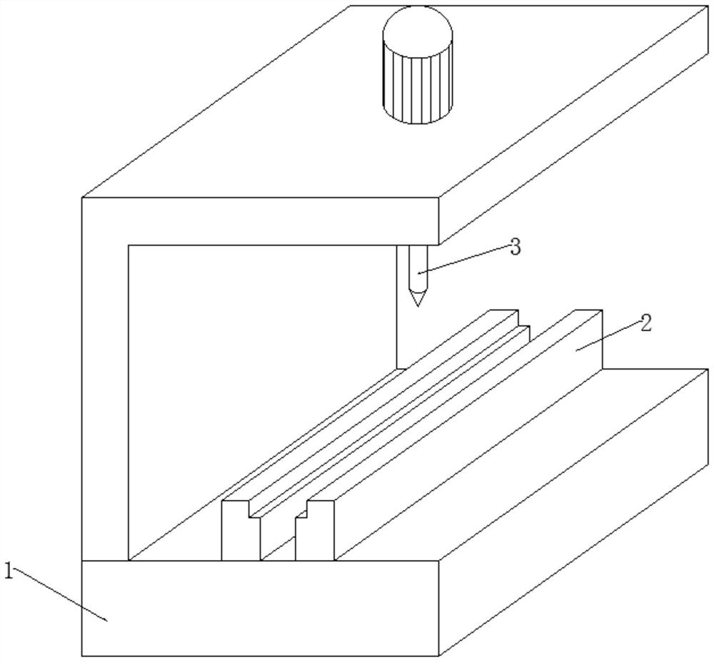
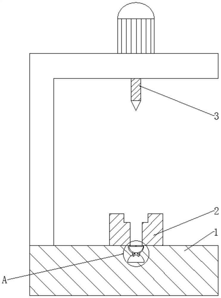
[0041] see Figure 1-3 , in an embodiment of the present invention, a punching device for network transformers, including a workbench 1, two limit seats 2 and a drill bit 3, the inner surface of the top side of the workbench 1 is close to the space between the two limit seats 2 The position of the groove is in the front and back horizontal direction, and there are several cleaning components 4 that can clean the work surface and are slidingly installed in equal rows;

[0042] Each group of cleaning components 4 includes a dust control component 401 that can control the ingress and egress of dust, a water storage component 402 that can store clean water, and a dust collection component 403 that can collect and absorb dust;

[0043] Here, the installation of the cleaning component 4 is set to slide for the convenience of taking out and cleaning after the cleaning component 4 has collected dust, for the next use.

[0044] In the embodiment of the present inve...

Example Embodiment

[0047] Example 2

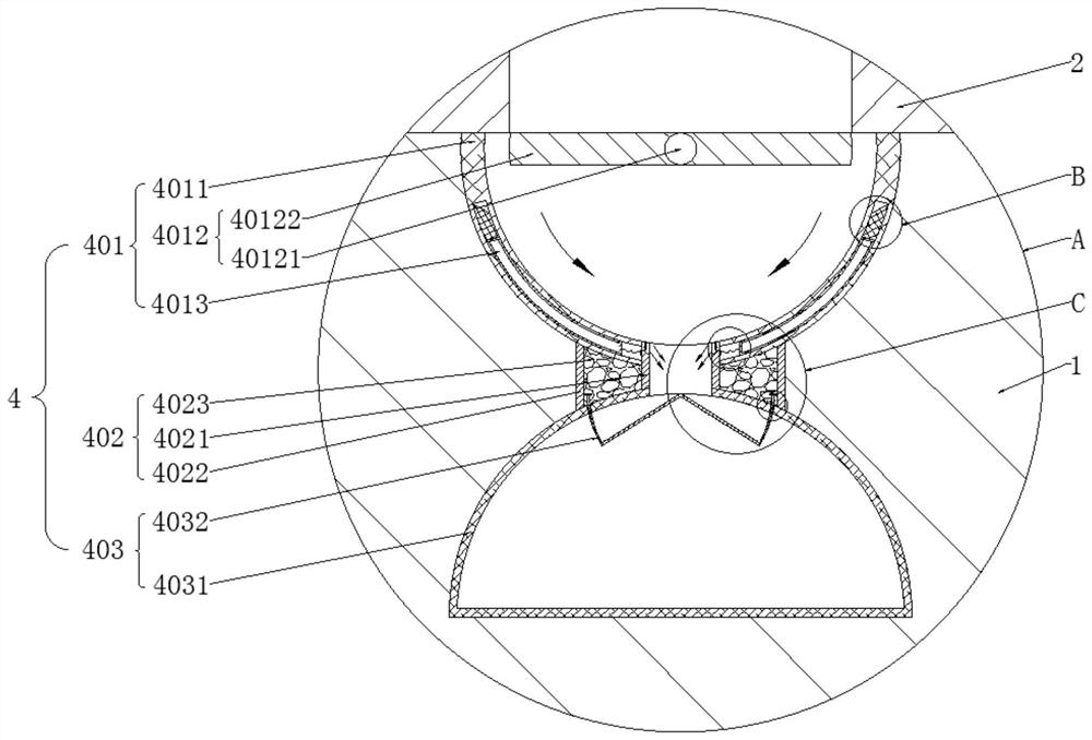
[0048] see Figure 3-6 Compared with Embodiment 1, this embodiment of the present invention differs from Embodiment 1 in that each set of dust control components 401 includes an upper spherical shell 4011, a balance component 4012 that can be introduced according to the weight of dust, and an auxiliary component that can assist in speeding up the introduction of dust. Component 4013.

[0049] In the embodiment of the present invention, the appearance of each upper spherical shell 4011 is hollow inside, hemispherical shape with a flat top and a convex bottom, and the inner diameter of each upper spherical shell 4011 is greater than the distance between the grooves between the two limit seats 2;

[0050] Here, the appearance of the upper spherical shell 4011 is set as a hollow inside, a hemispherical shape that is flat on the top and convex on the bottom, and the inner diameter is greater than the distance between the grooves between the two limit seats 2. T...

Example Embodiment

[0056] Example 3

[0057] see image 3 , Figure 5-7 Compared with Embodiment 1, this embodiment of the present invention differs in that each set of dust collecting assemblies 403 includes a lower spherical shell 4031 and a water control assembly 4032 that can control the ingress and egress of water.

[0058] In the embodiment of the present invention, the appearance of each lower spherical shell 4031 is a hemispherical shape with a hollow interior and a convex top and a flat bottom. Each set of water control components 4032 includes a rotating rod 40321, two inclined plates 40322, and two arc rods 40323 And two limit strips 40324;

[0059] Here, the appearance of the lower spherical shell 4031 is set as a hemispherical shape with a hollow interior, a convex top and a flat bottom, so that after the dust slides down the inner wall of the upper spherical shell 4011 and falls into the lower spherical shell 4031, it can be collected and blown out can be reduced.

[0060] In th...


PUM


Abstract

The invention provides drilling equipment for a network transformer. The drilling equipment comprises a workbench, two limiting bases and a drill bit, wherein a plurality of cleaning assemblies capable of cleaning a workbench top are installed at the position, close to a groove between the two limiting bases, of the inner surface of the top side of the workbench in the front-back horizontal direction in an equally adjacent and sliding mode, and each cleaning assembly comprises a dust control assembly capable of controlling entering and exiting of dust, a water storage assembly capable of storing clear water and a dust collection assembly capable of collecting and absorbing the dust. According to the drilling equipment for the network transformer, the workbench can have a self-cleaning function, in a drilling process of the network transformer, the dust is prevented from being left and accumulated in the groove between the two limiting bases for a long time, the dust can be cleared in time, stable clamping of the network transformer is guaranteed, the drilling error is reduced, and the accuracy is improved.

Description

technical field [0001] The invention relates to the technical field of network transformer production equipment, and more specifically, relates to a punching device for network transformers. Background technique [0002] In the prior art, when punching holes for transformer wiring boards, some of them use manual positioning for positioning and drilling. Since some transformer wiring boards are relatively small, the safety of workers is low when punching holes, and manual positioning is necessary. It is also inaccurate, resulting in unqualified punching of the wiring board, which affects later use. [0003] In view of the above problems, regarding the technical problem of inaccurate punching of the transformer terminal board, after a large number of searches, a transformer terminal board punching positioning device with a patent number of CN202021867185.3 was found, including a workbench and the top of the workbench The left side is fixed with a fixed plate, and the right si...

Claims


Application Information

Patent Timeline
IPC IPC(8): B23Q11/00B23B41/00
CPCB23B41/00B23Q11/0042B23Q11/0046
Inventor 杨长群
Owner 江西顺群电子科技有限公司
Why Eureka
Try Eureka