Rotary speed-limiting floating jet tool

A speed-limiting, tool-based technology, applied in the field of rotating speed-limiting floating injection tools, can solve the problems of reducing coiled tubing fatigue life, coiled tubing fatigue fracture, and increasing coiled tubing maintenance costs, so as to improve operating efficiency, improve injection quality, and ensure The effect of fatigue life

Active Publication Date: 2021-07-30
CHINA OILFIELD SERVICES
View PDF10 Cites 0 Cited by
  • Summary
  • Abstract
  • Description
  • Claims
  • Application Information

AI Technical Summary

Problems solved by technology

However, this will greatly reduce the fatigue life of the coiled tubing, causing premature fatigue fracture of some positions of the coiled tubing, which not only increases the maintenance cost of the coiled tubing, but also poses a greater safety hazard

Method used


Image

  • Rotary speed-limiting floating jet tool
  • Rotary speed-limiting floating jet tool
  • Rotary speed-limiting floating jet tool

Examples


Embodiment Construction

[0024] In order to make the purpose, technical solution and advantages of the present invention more clear, the embodiments of the present invention will be described in detail below in conjunction with the accompanying drawings. It should be noted that, in the case of no conflict, the embodiments in the present application and the features in the embodiments can be combined arbitrarily with each other.

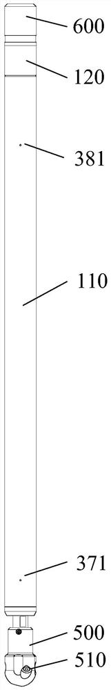
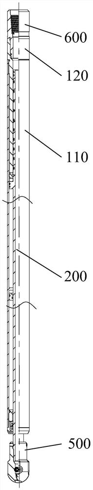
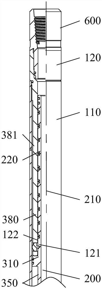
[0025] The rotating speed-limited floating injection tool provided by the embodiment of the present invention, such as Figure 1 to Figure 5 As shown, it includes: an outer cylinder; and a rotating shaft 200, which is installed in the outer cylinder in a rotatable and axially reciprocating manner. The rotating shaft 200 is provided with a liquid passage 210, and the front end of the rotating shaft 200 is provided with a centrifugal jet. The injection hole and the rear end communicate with the outer cylinder, the injection hole communicates with the liquid passage 210, and a s...


PUM


Abstract

The invention provides a rotary speed-limiting floating jet tool. The rotary speed-limiting floating jet tool comprises an outer cylinder and a rotating shaft, wherein the rotating shaft is installed in the outer cylinder in a rotatable and axial reciprocating movement mode, a liquid passing channel is formed in the rotating shaft, the front end of the rotating shaft is provided with a spraying hole used for centrifugal spraying, the rear end of the rotating shaft communicates with the outer cylinder, the spraying hole communicates with the liquid passing channel, and a speed limiting structure is arranged between the outer cylinder and the rotating shaft; the rotating shaft is arranged to be driven by liquid conveyed into the liquid passing channel from the outer cylinder, so that rotation and axial reciprocating movement are achieved; the speed limiting structure is used for limiting the rotating speed of the rotating shaft, and the spraying hole is used for centrifugally spraying the liquid outwards. The rotary speed-limiting floating jet tool is used in cooperation with a coiled pipe, key jet treatment can be carried out on a certain specific area without the need for the coiled pipe to take up and down, and the fatigue life of the coiled pipe is effectively guaranteed.

Description

technical field [0001] This article relates to the technical field of oil exploitation, and more specifically, relates to a rotating speed-limited floating injection tool. Background technique [0002] In the coiled tubing hydrojet operation, the coiled tubing is often lifted and lowered (up and down) to realize the focused spraying treatment on a specific area. However, this will greatly reduce the fatigue life of the coiled tubing, and cause premature fatigue fracture of some positions of the coiled tubing, which not only increases the maintenance cost of the coiled tubing, but also poses a greater safety hazard. Contents of the invention [0003] The embodiment of the present invention provides a rotating speed-limited floating injection tool, which is used in conjunction with the coiled tubing, and can realize focused injection treatment on a specific area without the coiled tubing moving up and down, effectively ensuring the fatigue life of the coiled tubing. [0004...

Claims


Application Information

Patent Timeline
Patent Type & Authority Applications(China)
IPC IPC(8): E21B7/18E21B21/00E21B41/00E21B12/00
CPCE21B7/18E21B21/00E21B41/00E21B12/00
Inventor 王景浩李伟智费春辉赵永顺姚旭洋陈咏涛
Owner CHINA OILFIELD SERVICES
Why Eureka
Try Eureka